23
MAINTENANCE SECTION
Assembly of the Motor
1.
If the shut–off mechanism was disassembled, install
the Control Shaft Seal (34) into the groove on the
Control Shaft (33).
2.
Insert the Control Shaft Spring (32) into the central
opening at the large end of the Control Bushing (29)
and insert the assembled Shaft, Seal end leading, into
the opening. The end of the Shaft must be encircled
by the Spring and the long groove must align with the
three crossholes for the Control Bushing Balls (31).
3.
Coat the Control Bushing Balls with Ingersoll–Rand
No.28 Grease and insert them into the crosshole
openings.
4.
Install the Control Valve Seal (28) on the Control
Valve (27) and place the Control Plate (26), large
open end leading, over the shaft of the Control
Bushing.
5.
Install the Backcap Front Spring (25) and the Control
Valve Assembly, seal end leading, over the shaft of
the Control Bushing. Install the Control Bushing
Seal in annular groove around the bushing shaft.
6.
Fit the Backcap Rear Spring (24) against the Control
Valve and thread the entire assembly, spring end lead-
ing, into the Backcap (23). Using a spanner wrench,
tighten the Control Bushing in the Backcap.
7.
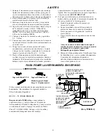
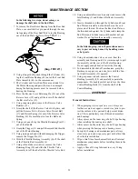
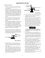
Using an arbor press and a piece of tubing that con-
tacts the outer ring of the bearings, press the Front
Rotor Bearing (45) into the Front End Plate (44) and
the Rear Rotor Bearing (39) into the Rear End Plate
(38). (Refer to Dwg. TPD1274.)
END PLATE
TUBING
BEARING
(Dwg. TPD1274)
8.
Stand the Rotor (42) on the table of an arbor press.
It should be upright on a flat metal plate having a
clearance hole for the shaft. The shaft with the hex
must be upward.
9.
Place a 0.001” (0.025 mm) shim on the upward
surface of the large portion of the rotor body. Using a
piece of tubing that contacts the inner ring of the
bearing, press the Front Rotor Bearing and Front End
Plate, End Plate leading, onto the shaft of the Rotor
until the End Plate contacts the shim. Remove the
shim. (Refer to Dwg. TPD1275.)
PRESSING PLUG
FRONT ROTOR
BEARING
ROTOR
PLATE WITH ROTOR
SHAFT CLEARANCE
FRONT END PLATE
0.001” (0.025 mm)
SHIM SPACE
(Dwg. TPD1275
)
10. Coat each Vane (43) with a thin film of oil and insert
a Vane into each of the rotor vane slots with the
straight edge of the Vane outward.
11. Install the Cylinder (41) over the Vanes and Rotor
making certain the End Plate Alignment Dowel (46)
enters the notch in the end face of the Cylinder.
12. Stand the assembly on an arbor press table so that the
rotor shaft on the front end plate end contacts the
table. Press the Rear End Plate Assembly, bearing
end trailing, onto the rotor shaft against the Cylinder.
Make certain the End Plate Alignment Dowel (40)
enters the notch in the end face of the Cylinder.
13. Stand the assembly on a table with the Front End
Plate Assembly upward.
In the following step, take all precautions neces-
sary to prevent being burned by handling warm
or hot parts.
14. Using an induction coil or oven, heat the Motor
Housing (1) until the motor opening is large enough
to be placed over the Cylinder. At that time, install
the Housing over the Cylinder and Front End Plate
making sure the radial End Plate Alignment Pin in the
Rear End Plate enters the notch in the Motor Hous-
ing.
15. Allow the assembly to cool and install the Backcap
Gasket (35) and the assembled Backcap (23).
16. Secure the Backcap to the Housing by installing the
three Backcap Mounting Screws (36) and Lock
Washers (37). Tighten each Screw between 45 and
50 in–lb (5.1 and 5.6 Nm) torque.
17. Install the Exhaust Deflector (22) in the bottom of the
handle of the Motor Housing and tighten it between
20 and 25 ft–lb (27 and 34 Nm) torque.
18. Thread the Inlet Bushing (2) into the bottom of the
handle of the Motor Housing (1) and tighten it be-
tween 30 and 35 ft–lb (40 and 47 Nm) torque.
19. Install the Throttle Rod Seal (9) in the groove on the
large hub of the Throttle Rod (8).
20. Install the Throttle Valve Seal (7) in the groove on the
large hub of the Throttle Valve (6).

