8
18-EB29D1-1F-EN
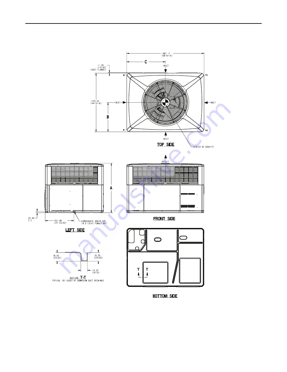
Figure 4. 3.5 — 5 TON MODELS
Note
:
The view labeled Bottom Side
represents the base as viewed looking
up from underneath the unit.
S
Stte
ep
p 2
2 —
— D
De
ette
errm
miin
ne
e U
Un
niitt C
Clle
ea
arra
an
ncce
ess
Page 1: ...unqualified person could result in death or serious injury When working on the equipment observe all precautions in the literature and on the tags stickers and labels that are attached to the equipmen...
Page 2: ...e ec ct tr ri ic ca al l c cu ur rr re en nt t a ar re e g gr ro ou un nd de ed d I If f g gr ro ou un nd di in ng g w wi ir re es s s sc cr re ew ws s s st tr ra ap ps s c cl li ip ps s n nu ut ts s...
Page 3: ...Step 2 Determine Unit Clearances 5 Step 3 Review Location and Recommendation Information 11 Step 4 Unit Installation 12 Step 5 Unit Startup 20 Sequence of Operation 21 Maintenance 22 Important Product...
Page 4: ...t 1 Check for damage after the unit is unloaded Report promptly to the carrier any damage found to the unit Do not drop the unit I Im mp po or rt ta an nt t To prevent damage to the sides and top of t...
Page 5: ...18 EB29D1 1F EN 5 Step 2 Determine Unit Clearances Figure 1 2 3 TON MODELS Note The view labeled Bottom Side represents the base as viewed looking up from underneath the unit...
Page 6: ...43 1 95 204 8 451 171 1 377 406 5 16 0 594 1 23 4 4TCC4036 61 7 136 38 9 86 27 7 61 43 7 96 205 7 453 172 0 379 414 3 16 3 697 6 27 5 4WCC4024 52 9 117 33 3 73 24 1 53 38 3 84 182 3 402 148 6 328 430...
Page 7: ...18 EB29D1 1F EN 7 Figure 3 2 3 TON MODELS S St te ep p 2 2 D De et te er rm mi in ne e U Un ni it t C Cl le ea ar ra an nc ce es s...
Page 8: ...N Figure 4 3 5 5 TON MODELS Note The view labeled Bottom Side represents the base as viewed looking up from underneath the unit S St te ep p 2 2 D De et te er rm mi in ne e U Un ni it t C Cl le ea ar...
Page 9: ...54 4 120 252 6 557 205 4 453 433 0 17 0 743 3 29 3 4TCC4060 78 0 172 46 3 102 34 9 77 59 0 130 265 8 586 218 6 482 414 0 16 3 635 0 25 0 4WCC4042 64 4 142 47 6 105 39 5 87 49 9 110 248 6 547 9 201 4 4...
Page 10: ...10 18 EB29D1 1F EN Figure 6 3 5 5 TON MODELS S St te ep p 2 2 D De et te er rm mi in ne e U Un ni it t C Cl le ea ar ra an nc ce es s...
Page 11: ...nstruction on converting the supply and return airflow covers to down airflow 3 The field assembled Roof Mounting Curb BAYCURB050A or BAYCURB051A or a field fabricated curb should be in place before t...
Page 12: ...the unit to direct roof water runoff 6 Seal all holes through exterior walls in accordance with local codes 7 Continue with the following installation sections to complete the installation Ductwork F...
Page 13: ...on during lifting Always test lift the unit to determine the exact unit balance and stability before hoisting it to the installation location 4 When the curb and air ducts have been properly installed...
Page 14: ...nce with local codes 11 Access and service clearances for the unit must be given careful consideration when locating the duct entrance openings Figures 1 to 6 provide unit dimensions 12 Continue with...
Page 15: ...repared by the manufacturer in order to provide detail regarding job layout only This drawing is not intended to be used as a basis to construct build or modify the item depicted in the drawing The ma...
Page 16: ...port Center Support required on all frame applications Angle Iron Frame Table 5 Typical Rooftop Down Airflow Application with Frame Return Air Roof Flashing Channel Iron Center Support center support...
Page 17: ...rproofed between the unit and the building When attaching ductwork to a horizontal unit provide a flexible watertight connection to prevent noise transmission from the unit to the ducts The flexible c...
Page 18: ...ch h Provide an approved weatherproof disconnect within close proximity and w wi it th hi in n s si ig gh ht t o of f t th he e u un ni it t If disconnect must be mounted to the cabinet the location s...
Page 19: ...ectric heater associated power wires and the W and X2 thermostat wires 7 Fig 3 demonstrates connection of the outdoor thermostat accessory only For further unit connection details refer to the other f...
Page 20: ...e used in the A AU UT TO O mode O Op pe er ra at ti in ng g P Pr re es ss su ur re e C Ch he ec ck ks s After the unit has operated in the cooling mode for a short period of time install pressure gaug...
Page 21: ...ought on when the indoor temperature drops 1 1 2 degrees below the thermostat setting T TS SH H 2 2 contacts close providing power to the W W terminal on the indoor thermostat and to the supplementary...
Page 22: ...ters of the same type and size D Do o n no ot t a at tt te em mp pt t t to o c cl le ea an n d di is sp po os sa ab bl le e f fi il lt te er rs s Permanent type filters can be cleaned by washing them...
Page 23: ..._____________________________________________________ Service Information Call your installing dealer if the unit is inoperative Before you call always check the following to be sure service is requir...
Page 24: ...a global business committed to a world of sustainable progress and enduring results ingersollrand com The AHRI Certified mark indicates Ingersoll Rand participation in the AHRI Certification program...