Triton Go Product Manual |
Wiring and Connections
INGENIA | 05/29/2017
79
70
http://ingeniamc.com/support
result in hall sensors wrong commutation errors or encoder loss of counts. For these applications we
recommend:
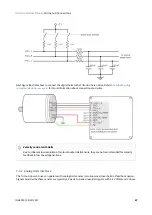
• Use a common mode choke on the motor phases. This single action can reduce common mode noise
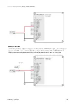
drastically and will solve most problems. See recommended wiring in
Motor and shunt braking resistor
•
Ensure the motor housing is well connected to protective earth and the system chassis (PE).
•
If possible, minimize power supply voltage. This will also minimize the electromagnetic noise generated
by the motor switching.
•
Add additional RC low pass filters on the feedback inputs. The filter should attenuate at a frequency
above the maximum speed signal to prevent loss of counts and signal distortion. Preferably use resistors
with low values to prevent distortion to the servo drive input circuit at low frequency (< 500
Ω
). Use
ceramic capacitors with good quality dielectric, like C0G.
For further information contact
7.5 I/O connections
The Triton Go Servo Drive provides various inputs and output terminals for parameter observation and drive
control options. These inputs can also be used for some feedback purposes (see
The input and output pins are summarized below:
• 4 x
5 V general purpose non-isolated single ended digital inputs
(GPI1, GPI2, GPI3, GPI4).
• 2 x
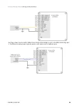
5 V high-speed non-isolated differential digital inputs
• 1 x
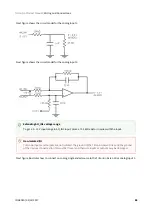
0 ~ 5 V single ended 12 bits analog input
• 1 x
±10 V differential 12 bits analog input
(AN_IN2).
•
5 V non-isolated digital outputs
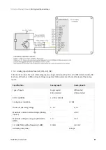
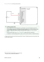
Apart from the general purpose inputs, Triton Go has a dedicated analog input for measuring the
.
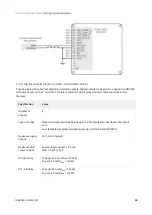
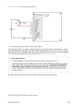
7.5.1 General purpose single ended digital inputs interface (GPI1, GPI2, GPI3, GPI4)
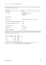
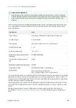
The general purpose non-isolated digital inputs are ready for 5 V levels, but are 24 V tolerant. Next table show
their electrical specifications.
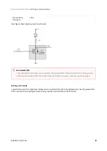
Motor brake input
Digital outputs (GPO1, GPO2, GPO3 and GPO4) can also be used as a
.
Wiring recommendations
Wiring recommendations for I/O signals are the same than for feedback signals. Detailed information
about good wiring practices can be found in
Feedback wiring recommendations

