VarioCAM
®
HD head
7. Start-up
User Manual
© InfraTec GmbH 2016
19
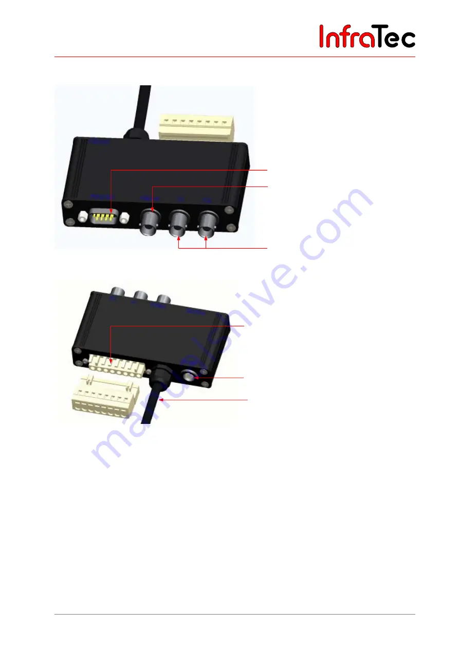
Connecting the breakout box
Fig. 14
Breakout box (RS232, BNC: FBAS, Trigger)
Fig. 15
Breakout box reverse
7.6
Trigger channels VarioCAM
®
HD head
7.6.1
Trigger function
Triggering uses the Ethernet to affect the 16bit IRB data transmission. The trigger signal (5 V) is fed in via
the BNC sockets of the breakout box identified with T1 and T2 from where it is forwarded to the
VarioCAM
®
HD head (right socket) using the connecting cable with 14-pin LEMO connector.
Commercially available BNC cables can be used in order to connect the trigger signal sources to the
breakout box.
■
T1
Trigger channel 1 is used by the IRBIS
®
3 software.
■
T2
Trigger channel 2 is reserved for the SDK and further specific applications.
BNC video port (PAL/NTSC-FBAS)
Serial interface (RS232)
Trigger T1, T2 (configurable)
LEMO socket, 14-pin for connection to
the wall plug transformer
Cable to the VarioCAM
®
HD head (with
14-pin LEMO connector)
Terminal strip (analog output)
InfraTec
Summary of Contents for VBIP-G
Page 2: ...I n f r a T e c ...


