background image

INFOSEC UPS SYSTEM – 4 rue de la Rigotière – 44700 Orvault – France – www.infosec-ups.com 

Hot Line Tel : +33 (0)2 40 76 15 82 – fax : +33(0)2 40 94 29 51 – [email protected] – 04 09 AA XX 201 19


23 


5.


Bundled Software Installation Guide 

5.1 Hardware Installation 


1.


Connect the male connector of RS232 cable to the UPS communication port.


2.


Connect the female connector of the RS232 cable to a dedicated RS232 port of the 

computer. 

3.


For optional interface cards, you may refer to Chapter 6 for installation. 

5.2 Software Installation 

Please refer to the user’s manual of the software for installation


6.


Customer Options Slots 


6.1 R2E (2nd RS-232) card 


CN1 is for RS232 DB9. 


For communication protocol, please refer to Chapter 

0(2.4.1)  


Installation Position: slot1 (CHA-CN4) or slot 2(CHB-

CN5). 

6.2 RSE (RS-485) card 


CN1 is for the function of the terminal resistor.   

Short pin1-2 to enable the function and short pin2-3 

to disable it.   


CN2 for RS485 and CN3 for remote power. 


Definition 


Installation Position: slot1. 

6.3 USE(USB) card 


CN1 for USB. 


Definition  


Comply with USB version 1.0,1.5Mbps 


Comply with USB HID Version 1.0. 


The Pin Assignments of the USE card:   


Installation Position: slot1

CHA-CN3

  or slot 2

CHB-CN4

CN3 

CN2 

 Ground 

 A/Data+ 

 B/Data- 

 AC+ 

 AC- 

Summary of Contents for E6 LCD-RT

Page 1: ...USER MANUAL 5 6 8 10KVA One phase to one phase 10KVA Three phase to one phase Parallel Redundancy On Line UPS ...

Page 2: ...Installation and Operation 10 3 1 Unpacking 10 3 2 Selecting Installation Position 11 3 3 Installation of Accessories Kit 11 3 4 Terminal Block Explanation UPS connection 11 3 4 Terminal Block Explanation UPS connection 12 3 5 Operation Test and Installation Instruction 15 4 Troubleshooting Guide 22 4 1 Trouble Shooting 22 5 Bundled Software Installation Guide 23 5 1 Hardware Installation 23 5 2 S...

Page 3: ... eliminate any overheating of the UPS keep all ventilation openings free from obstruction and do not store things on top of the UPS Keep the UPS 30 cm away from the wall Make sure the UPS is installed within the proper environment as specified 0 40 and 0 90 non condensing humidity Do not install the UPS in direct sunlight Your warranty may be void if the batteries fail Do not install in an environ...

Page 4: ...owed during Installation and Maintenance of the UPS and Batteries Disconnection Device CAUTION A disconnect switch shall be provided by others for ac output circuit To reduce the risk of fire connect only to a circuit provided with branch circuit over current protection for 32 amperes for 5 6Kva 40 amperes for 8Kva and 50 amperes for 10Kva rating in accordance with the National Electric Code CAUTI...

Page 5: ...er mode once overload condition ceases Should the output becomes short circuit the UPS holds the system and cuts the output automatically till the short circuit situation is removed manually Should the unit become overheated the internal thermal Switch will detect the heat and switch to bypass mode and vice versa Fully digitalized control circuit built in the UPS may upgrade the functionality Of t...

Page 6: ...city if the input voltage is 160 280Vac 2 2 Symbols on the LCD Display Panel Item Symbol Description 1 LINE Utility or Bypass Source 2 Battery Low 3 Battery Abnormal 4 UPS Overloading 5 UPS Working in specified mode 6 A Blackout Transfer occurred in UPS Output 7 Bypass Input Abnormal UPS fails to transfer to bypass Bypass Abnormal at ECO mode 8 Utility Input Abnormal 9 OFF UPS Shutoff 10 LINE OFF ...

Page 7: ...or 32 Er15 Wrong Procedure to enter Maintenance Mode 33 Er16 Output Parameters Set Error in Parallel System 34 Er17 ID Numbers are in conflict in Parallel System or ID number Error in single unit 35 Er21 Parallel communication error communication wire disconnected or failure to find ID1 UPS in parallel system 36 Er24 CVCF mode with Bypass input 37 Er27 The UPS must be operated in normal mode in pa...

Page 8: ... run under redundancy mode Green LED steadily lights up to indicate that the Utility input voltage is within the window the LED flashes flickeringly to indicate that the Utility input voltage is within the acceptable window Green LED lights up to indicate Bypass Input is normal UPS ON Alarm Silence Go to previous page or change the setting of the UPS To re confirm the change of UPS Setting Go to n...

Page 9: ...FOSEC UPS SYSTEM 4 rue de la Rigotière 44700 Orvault France www infosec ups com Hot Line Tel 33 0 2 40 76 15 82 fax 33 0 2 40 94 29 51 hotline infosec fr 04 09 AA XX 201 19 8 2 3 2 Rear Panel Explanation ...

Page 10: ...S status With optional interfaces cards which contains R2E 2nd RS232 RSE RS485 USE USB DCE Dry Contact as well as SNMP card you may combine them according to your demand However the R2E card RSE card and USE card are prohibited to be used simultaneously The bundled software of the UPS is compatible with many operating systems such as Windows 98 2000 ME NT and XP For other applications like Novell ...

Page 11: ...Take the UPS out of the PE foam Unwrap the UPS Standard Package includes 1 set of Quick Start Manual 1 set of User s Manual 1 set of UPS communication software with RS232 cable 1 set of Metal Accessories Kit Package for the UPS with Isolation transformer dual input Ditto but with additional 3pcs wire No 7 Package for the UPS without isolation transformer but dual input Ditto but with additional 1p...

Page 12: ...UPS and extend the life of the UPS Please follow the advice below 1 Keep at least 30cm 12 inches clearance from the rear panel of the UPS to the wall 2 Do not block the air flow to the ventilation openings of the unit 3 Please check the installation site to avoid overheat and excessive moisture 4 Do not place the UPS in an environment near dust corruptive or salty material or flammable objects 5 D...

Page 13: ...de the power source when the UPS is working under Utility mode G1 the terminal for UPS Input Ground L21 N22 the terminals for UPS Output G2 the terminal for UPS Output Ground For E6 LCD RT 10K Single phase in standard use main input and by pass line are common so there is a shunt between L11 L12 L11 N1 Used only in case where the main input and by pass line are not common the terminal for Bypass I...

Page 14: ...10 mm E6 LCD 10 K RT 3 1 4 x 63 A 5 x 10 mm 2 x 50 A 3 x 10 mm WARNING If the connecting of neutral wire N and Line wire L is in order the UPS do not change neutral rate of installation A circuit breaker connected before the UPS will operate for an insulation fault after the UPS Sensibility of the circuit breaker takes into account the UPS current leak about 15mA and connected computers We recomme...

Page 15: ...al battery bank E6 LCD 5000 RT The batteries are fitted inside UPS bank For all other UPS from 6000 to 10kVA the batteries are fitted inside an external battery bank Please refer to the battery bank user s manual for a correct procedure Refer to the following chart for external battery bank connection Model Maximum Current Conductor Section 6KVA 25A 6 mm 8KVA 33A 6 mm 10KVA 41A 6 mm ...

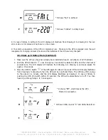
Page 16: ...akers of the UPS Utility and Bypass Inputs and then the UPS starts up Green LEDs light up to show the Utility and Bypass Inputs are normal and the LCD display with parallel function will illustrate from drawing A1 drawing A2 to drawing B Otherwise the LCD display will illustrate from drawing A2 to drawing B A1 A2 B 5 Then the UPS is on Bypass Mode now and it will proceed self test automatically If...

Page 17: ...d Start 1 Make sure the UPS you have has already been installed at least 1 set 20pcs of 12V batteries 2 Push the UPS On Switch once for approx 5 seconds to awake the UPS and then the buzzer sounds twice The LCD display will illustrate from drawing A to drawing G and keep awake for approx 15 seconds 3 Press the UPS On Switch of the UPS again for about 3 seconds till the LCD display illustrates from...

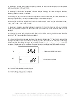
Page 18: ...ay will illustrate as Drawing C Voltage from Utility Input Drawing I1 Voltage from Bypass Input Drawing J Frequency from Utility Input Drawing K Frequency from Bypass Input Drawing L UPS Output Voltage Drawing M UPS Output Frequency Drawing N UPS Output Load Drawing O UPS Battery Voltage Drawing P UPS Inner Temperature I1 It shows voltage comes from Bypass Input J It shows frequency from Utility I...

Page 19: ...e UPS settings The LCD display will show in consequence between Drawing Q1 buzzer Drawing R1 Self test Drawing S1 Bypass Voltage Windows Drawing T Output Frequency Synchronization Window Drawing U Inverter Output Voltage Drawing V1 UPS Operation Mode Drawing W Output Voltage Micro Tune Value Drawing X UPS Id Drawing Y Parallel function status R1 It shows self test is NOT on R2 It shows self test i...

Page 20: ...or UPS Warning and self test OFF As drawing R1 or self test ON as drawing R2 UPS will execute battery test for 10 seconds If the self test is successful it will show as Drawing E1 otherwise it will show as drawing E2 error message in the same time 3 5 5 UPS Default Settings and their alternatives 1 Make sure the UPS is not On yet Press On Switch and scroll down key pads simultaneously for approx 3...

Page 21: ... 3 9 Drawing X means a specified address position of the UPS when the UPS is in Parallel mode The settable numbers are from 1st to 4th The number must be 1st if the UPS is not in parallel 10 Drawing Y means the parallel function status The P 01 means parallel function disabled and the P 02 means parallel function enabled 11 When all the setting changes are done you have to press enter key Pad to s...

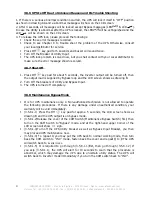
Page 22: ...then the output load is supplied by Bypass loop and the LCD screen shows as drawing B 2 Turn Off the breakers of Utility and Bypass Input 3 The UPS is turned off completely 3 5 8 Maintenance Bypass Mode It is for UPS maintenance only A Non authorized technician is not allowed to operate the following procedures If there is any damage under unauthorized condition your warranty will be void immediat...

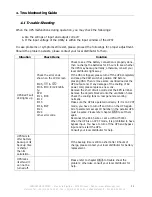
Page 23: ...ease turn off the UPS completely and keep the CAM switch at position INV before pressing CB3 Then remove some uncritical load at the UPS output end If any damage of the coating of AC power cord please replace a new one Remove the short circuit occurred at the EPO terminal Remove the objects blocked onto the ventilation holes Check the cooling fans on rear panel are working normally Make sure the U...

Page 24: ...ase refer to the user s manual of the software for installation 6 Customer Options Slots 6 1 R2E 2nd RS 232 card CN1 is for RS232 DB9 For communication protocol please refer to Chapter 0 2 4 1 Installation Position slot1 CHA CN4 or slot 2 CHB CN5 6 2 RSE RS 485 card CN1 is for the function of the terminal resistor Short pin1 2 to enable the function and short pin2 3 to disable it CN2 for RS485 and...

Page 25: ...ween pin9 and pin10 for 5 seconds The capacity of each relay contact is 40Vdc 25mA Installation Position slot1 CHA CN7 or slot 2 CHB CN8 Flexible signal output for N C Normal close or N O Normal open contact by shorting pin1 2 or pin2 3 from JP1 5 The shutdown function will be enabled in 1 minute after blackout occurs if the pin1 2 of both CN1 and CN6 be shorted by cap Or the shutdown function can...

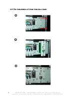
Page 26: ...STEM 4 rue de la Rigotière 44700 Orvault France www infosec ups com Hot Line Tel 33 0 2 40 76 15 82 fax 33 0 2 40 94 29 51 hotline infosec fr 04 09 AA XX 201 19 25 1 2 3 6 6 The Installation of those Interface Cards ...

Page 27: ...lt Data specified on LCD Input voltage Input frequency Output voltage Frequency voltage charge level Voltage battery internal Temperature Self diagnostics In mains mode from control panel by software and auto test 24h PROTECTION Short circuit off mode immediately Over heating Mains mode Bypass Transfer Battery Mode Automatic shutdown Low battery Alarm and automatic stop EPO Stop immediate Battery ...

Reviews: