6
PSU LED:
PSU LED:
On
(
)
•
green
Powering up
6-1.
C
onnect the power cords to the power socket (in
) on both PSUs.
Connecting the power cord
blue
7-2.
You may control the RAID system using the firmware menu (through the RS-232C
interface) or the SANWatch GUI software (through the Ethernet or host PC interface).
For more tools and their details, refer to the manuals in the CD-ROM.
Firmware menu:
1. Connect your computer to the RAID system through an RS-232C cable.
2. Open a terminal emulation software such as VT-100 on your PC.
3. Configure the serial port as shown in the previous section and connect the RAID system.
The main firmware menu will appear.
4. Use the cursor keys to select the menu.
SANWatch:
1. Connect the RAID system to a remote computer through the Ethernet port or to a
host PC through the host links.
2. Install the SANWatch software suite, included in the CD-ROM, into your computer.
3.
4. On SANWatch, select the RAID system from the Connection View.
5. Go to the Tasks section and select the License Information and generate a
License Application File.
6. Visit http://www.infortrend.com/DSLS to register software license. The license number
is attached in the software license envelop.
7. Activate software features using the license information and continue operating
SANWatch.
Accessing management tools
Install EonPath (multi-pathing driver)
ONLY
to Windows 2003 based servers. Other
OS use their build-in native multi-pathing driver.
The functions and settings available in each tool are different from each other.
For more details, consult the respective manuals.
Note:
• Host PC (in-band connection):
users will access the RAID system from the host servers
through the host links.
•
Ethernet Management port (Out-of-band connection):
You can access the RAID system
from a remotely connected computer through the Ethernet cable. You need to obtain the IP
address, static IP address or DHCP, from your network administrator. If neither is available,
use the default address < 10.10.1.1>.
•
Serial port:
You can access the RAID
system from a directly connected
computer through the RS-232C port.
(The serial cable is provided as an
accessory for dual-controller models.
For single-controller models, the serial
cable is user-supplied.)
Serial port setting:
Baud rate:
38400
Data bit:
8 bit
Parity:
none
Stop bit:
1
Flow control:
hardware
6-2. Powering up the equipment
1. Power up the networking devices.
2. Power up the JBODs (if applied) by pressing the power switches on the rear panel.
3. Power up the RAID system by pressing both power switches (shown above in
) on the
rear panel.
4. Power up the application servers.
green
Front panel LEDs:
0
2
4
6
8 10
1
2
14
6-3.
Observe the front of the enclosure. If the LED indicators show different status than
described below, or if you hear an audible alarm, contact customer support.
Verifying the status LEDs (front of enclosure)
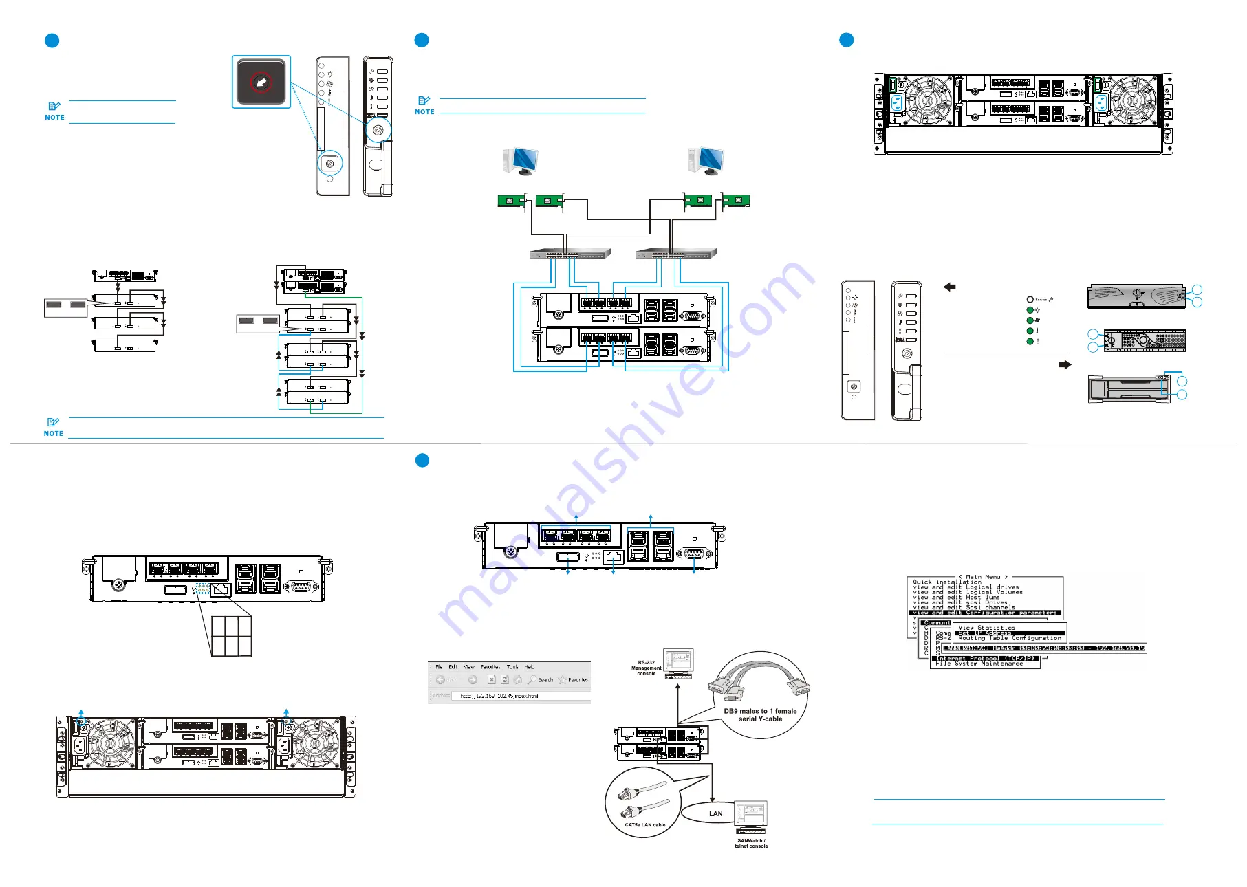
Drive tray:
7-1. Overview of management interfaces
Connecting to Management Interfaces
7
Managing and monitoring the RAID system is available through three types of interfaces.
Refer to the sample figures below on controller host ports and management interfaces:
Host board host ports
JBOD SAS
expansion
Serial port
Ethernet
management port
Onboard iSCSI host ports
6-4.
Observe the rear of the enclosure. If the LED indicators show different status than
described below, or if you hear an audible alarm, contact customer support.
Verifying the status LEDs (rear of enclosure)
Controller LEDs:
1. Ctrl Status LED:
On
(
)
2. C_Dirty LED:
Off
3. Temp LED:
Off
green
1 2 3
4 5 6
4. CBM Status LED:
On
(
)
or Off
5.
Hst Bsy LED:
On
(
)
6.
Drv Bsy LED:
On
(
)
green
green
green
PSU LED
PSU LED
The below diagrams show the recommended connections among the RAID system,
switches, and the hosts.
For more information, refer to the hardware manual available in the product CD-ROM.
Making host connections
Host link cables are not included in the product package.
5
4
JBOD Connections
4-1. Setting the JBOD IDs
Use a small flat blade screwdriver to set the
JBOD enclosure ID(s). A different ID number
must be allocated for each JBOD.
RAID systems are assigned
with ID “0" by default.
Dual controller models
st
• RAID system top SAS exp. – 1 JBOD top SAS-IN
st
nd
• 1 JBOD top SAS-OUT – 2 JBOD top SAS-IN
st
• 1 JBOD bottom SAS-IN port – 2nd JBOD bottom SAS-OUT
• RAID system bottom SAS exp. – last JBOD bottom SAS-IN
Single controller models
• RAID system SAS exp. – 1st JBOD SAS-IN
• 1st JBOD SAS-OUT– 2nd JBOD SAS-IN
To ensure redundancy, dual controller SAS expansion must be connected to the opposite
ends of daisy-chained JBODs (eg. first JBOD and last JBOD).
System LED:
Green
Service LED:
Off
Power LED:
Green
Cooling fan LED:
Green
Thermal LED:
Green
/
3U / 36-bay model
3.5 inch
2.5 inch 3U / 36-bay model only
2.5 inch
1. Drive Activity LED:
On
= Drive plugged-in
(
)
Flashing
= R/W activity (
)
Blue
Blue
2. Power Status LED:
On
(
)
Failure
(
)
Green
Red
0
2
4
6
8 10
1
2
14
0
2
4
6
8 10
1
2
14
Service
1st JBOD
Last JBOD
2nd JBOD
.
.
.
IN
OUT
1st JBOD
Last JBOD
2nd JBOD
.
.
.
IN
OUT
0
2
4
6
8 10
1
2
14
4-2. Making the connections
Connect the cables between the RAID system and the JBOD(s).
3U / 36-bay model
Mute /
Service
Service
Mute /
Service
0
2
4
6
8 10
1
2
14
2
1
2
1
2
1
Single Controller RAID System
Dual Controller RAID System
Switch
Switch
RAID System
Host
Host
HBA 1 HBA 0
HBA 1
HBA 0


