Quick Installation Guide
1
Unpacking the Subsystem
4
Quick Installation Guide
Check the included
Unpacking Checklist
and verify the model name and shipping
contents against the checklist.
The A12E-G2121 subsystem supports SATA-I,
SATA-II, and PATA hard drives. If you are going
to use PATA drives in your system, optional
dongle kits must be installed in each drive tray.
Hard drive installation without a dongle kit
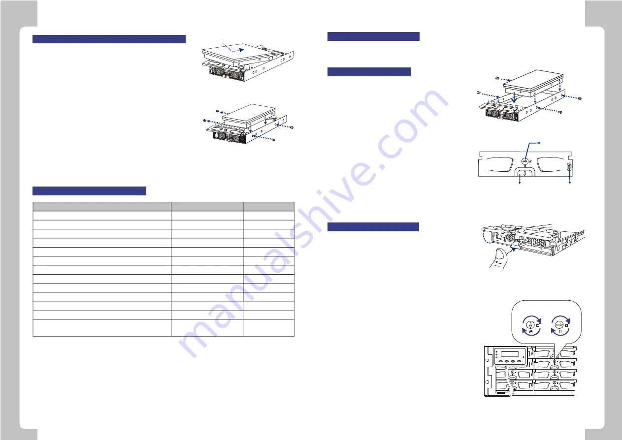
1. Place the SATA-I or SATA-II hard drive into
the drive tray. Make sure that the hard drive is
oriented in such a way that the Serial ATA
(SATA) connector is facing the back of the
drive tray.
2. Adjust the drive's location until the mounting
holes in the drive canister are aligned with
those on the hard drive. Secure the drive with
four (4) of the supplied 6/32 flat-head screws.
(See
Figure 1
)
Hard Drive Installation
Figure 1:
Installing the SATA Drive
Figure 2:
Drive Canister Front View
Key-lock
Front Button
LED Indicators
1. Turn the key-lock to the unlocked position.
The key-lock is unlocked if the groove on its
face is in a horizontal orientation. (See
Figure 2
)
2. Open the front flap on the drive tray by
pushing the release button on the
front of the drive tray. (See
Figure 3
)
3. Line the drive tray up with the slot in which
you wish to insert it. Make sure that it is
resting on the rails inside the enclosure. Once
the drive tray is lined up with the slot, gently
slide it in. This should be done smoothly and
gently.
4. Close the front flap on the drive tray. Make
sure the front flap is closed properly to ensure
that the SATA connector at the back of the
drive tray is firmly connected to the
corresponding connector on the back plane
board. If the front flap is not closed properly,
then the connection between the HDD
and the subsystem will not be secure. To lock
the flap in place, turn the key-lock until the
groove on its face is in a vertical orientation.
(See
Figure 4
)
Drive Tray Installation
Figure 3:
Opening Drive Tray Front Flap
PWR
MUTE
BUSY
ATTEN
ESC
ENT
Lock
Unlock
Figure 4: Drive Tray Key-Lock Rotation
2
RAID function Limitations
Options
Default Value
64-bit LBA support (>2TB)
Number of LD
Number of LV
Number of partitions per LD
Number of LUN's per channel ID
Number of LUN's
Optimization mode
Caching mode
Stripe size (Optimization for Sequential I/Os -RAID 5)
Auto-assign Global Spare
LD capacity -Optimization for Sequential I/Os
Number of Media Scan task schedules
Yes
16(Max.)
8(Max.)
8(Max.)
32(Max.)
128(Max.)
Seq. I/O or Random I/O
Write-Thru or Write-Back
4/8/16/32/64/128/256KB
Enable/Disable
64TB(Max.)
16(Max.)
Yes
16
8
8
8
---
Seq. I/O
Write-Back
128KB
Disable
64TB (Max)
16
1. For PATA drives, connect the ATA and power cables
from the dongle kit to the hard drive. Make sure that
these connections are secure and will not come loose.
(See
Figure 11
)
2. Once the dongle kit connectors are firmly attached to
the hard drive, place the hard drive into the drive tray.
3.
Adjust the drive's location until the mounting holes in
the drive canister are aligned with those on the hard
drive. Secure the drive with four (4) of the supplied
6/32 flat-head screws. (See
Figure 12)
Once the hard drives are installed into drive trays, install
all twelve (12) drive trays into the subsystem. Please
refer to the drive tray installation procedure in this
installation guide or that in the user's manual that will be
included in the Product Utility CD.
Hard Drive Installation with Dongle Kit
Figure 11:
PATA Hard Drive Connectors
Figure 12:
Inserting the PATA Drive
Feature
---
128 drives(Max.) / 512MB
or above
Number of LD (RAID5)member drives related to
memory capacity
For more details on the Firmware, please refer to the firmware
Generic Operation Manual
that came with your "Product Utility CD".


