background image

ERS 610

4

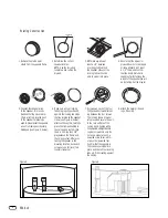
Existing Construction 

1. Remove the plastic paint 

shield from the speaker frame.

2. Determine the correct 

speaker location.

NOTE:

Use the included 

template when cutting the 
drywall.

Template

Ceiling Joist

Ceiling Joist

3.

NOTE:

Always allow at 

least a 1/2" between 
a ceiling stud/joist and 
the speaker cutout, or the 
locking tabs will not be 
able to swivel into place.

4. Ensure that the drywall or 

plywood board or other appro-
priate wallboard is at least 
a 1/2" thick, and confirm 
that the board material is 
capable of withstanding the
weight of the speaker you will
be installing. Cut the drywall.

5. Connect the speaker wires 

to the speaker. It is recom-
mended that the nylon cable-
strain relief tab, located next 
to the speaker terminals, be
used to help prevent the speaker
wires from being accidentally
dislodged (see Figure 5, below).

6. Make sure all four locking

tabs are properly positioned
against the locking tab stops
that are located on the speaker
frame (see Figure 6, below).
After confirming this, carefully
place the frame assembly in
the ceiling and confirm that
there is no more than 1/8"
play between the frame and
the ceiling cutout. After posi-
tioning the speaker in the
mounting location, back each
screw out one full turn (turn
counterclockwise).

7. Screw down each of the four

Phillips-head screws, alternat-
ing between the four screws.
The locking tabs will swivel
into place and secure the unit
to the rear surface of the 
ceiling. Hand-tighten with a
nonpowered, straight-handle
regular screwdriver only. Do
not use a socket wrench, a
powered screwdriver, a drill 
or any other powered tool.
Confirm that the speaker is
firmly and securely held in
place and that all four locking
tabs are firmly resting against
the ceiling.

8. Attach the metal grille and

logo, if desired.

Figure 6.

Figure 5.

Summary of Contents for ERS 610

Page 1: ...ERS SERIES ERS 610 Owner s Guide ...

Page 2: ...erhead view shows a typical home theater system arrangement Figure 3 This overhead view shows a 6 or 7 channel home theater system arrangement Left right rear channels are for a 7 channel system Center rear channel is for a 6 channel system NOTE An Infinity powered subwoofer will add impact and realism to both music and film soundtracks Contact your Infinity dealer for recommendations on subwoofer...

Page 3: ...g speaker was designed to be easily installed However if you are unable to clearly and fully under stand and follow the instructions in this manual or if you are unsure of your ability to properly install these loudspeakers please contact your dealer or a qualified installer Tools Needed SPEAKER CONNECTIONS ConnectionTips Figure 4 Wire Length Recommended Size Up to 100 ft 16 gauge Greater than 100...

Page 4: ...cidentally dislodged see Figure 5 below 6 Make sure all four locking tabs are properly positioned against the locking tab stops that are located on the speaker frame see Figure 6 below After confirming this carefully place the frame assembly in the ceiling and confirm that there is no more than 1 8 play between the frame and the ceiling cutout After posi tioning the speaker in the mounting locatio...

Page 5: ... ment s instructions to ensure that the subwoofer if you have one output is turned on and that the speakers are set to Small in each mode Tweeter Level Control In most typical listening rooms this switch should be left in the neutral or 0 position This setting will deliver the most neutral and balanced sound In some extreme cases it may be desirable to slightly boost or cut the tweeter s output de...

Page 6: ...r Nominal Impedance 8 Ohms Crossover Frequencies 700Hz 2 000Hz 24dB octave Low Frequency Driver 7 3 4 x 3 3 8 197mm x 85mm MRS Midrange Drivers Dual 3 CMMD 75mm High Frequency Driver 1 25mm CMMD External Diameter 12 3 4 323mm Mounting Cutout Diameter 11 3 8 289mm Mounting Depth 5 5 8 142mm Weight net 8 lb 3 6kg SPECIFICATIONS ...

Page 7: ...NOTES ...

Page 8: ... Pro Logic are registered trademarks of Dolby Laboratories DTS is a registered trademark of DTS Inc Part No BO 16353 01 8 07 Declaration of Conformity We Harman Consumer Group Inc 2 route de Tours 72500 Château du Loir France declare in own responsibility that the products described in this owner s manual are in compliance with technical standards EN 55013 2001 A1 2003 EN 55020 2002 A1 2003 EN 610...

Reviews: