


Design Guide
8 of 48
V 1.0
2018-06-06
XDPL8218 design guide
For high power factor flyback converter with constant voltage output
Flyback MOSFET and secondary main output diode selection
4
Flyback MOSFET and secondary main output diode selection
The CoolMOS
TM
P7 MOSFET series is the latest CoolMOS
TM
product family and targets customers looking for high
performance and at the same time being price sensitive. Through optimizing key parameters (C
oss
, E
oss
, Q
g
, C
iss
and V
GS(th)
); integrating Zener diode for ESD protection and other measures, this product family fully addresses
market concerns in performance, ease-of-use, and price/performance ratio, delivering best-in-class
performance with exceptional ease-of-use, while still not compromising on price/performance ratio. The 700 V
and 800 V CoolMOS
TM
P7 series have been designed for flyback and could also be used in PFC topologies.
MOSFET drain-source breakdown voltage V
(BR)DSS
= 800 V is selected in this design example based on V
AC,max
of
305 V
rms
and transformer design in
Section 3
Before selecting which MOSFET drain-source on-resistance at room temperature R
ds(on),25°C
is to be used, the
maximum primary rms current I
pri(rms),max
has to be estimated based on:
𝐼
𝑝𝑟𝑖(𝑟𝑚𝑠),𝑚𝑎𝑥
≈ 𝐼
𝑝𝑟𝑖(𝑝𝑘),𝑚𝑎𝑥
∙ √
𝑘
3
(9)
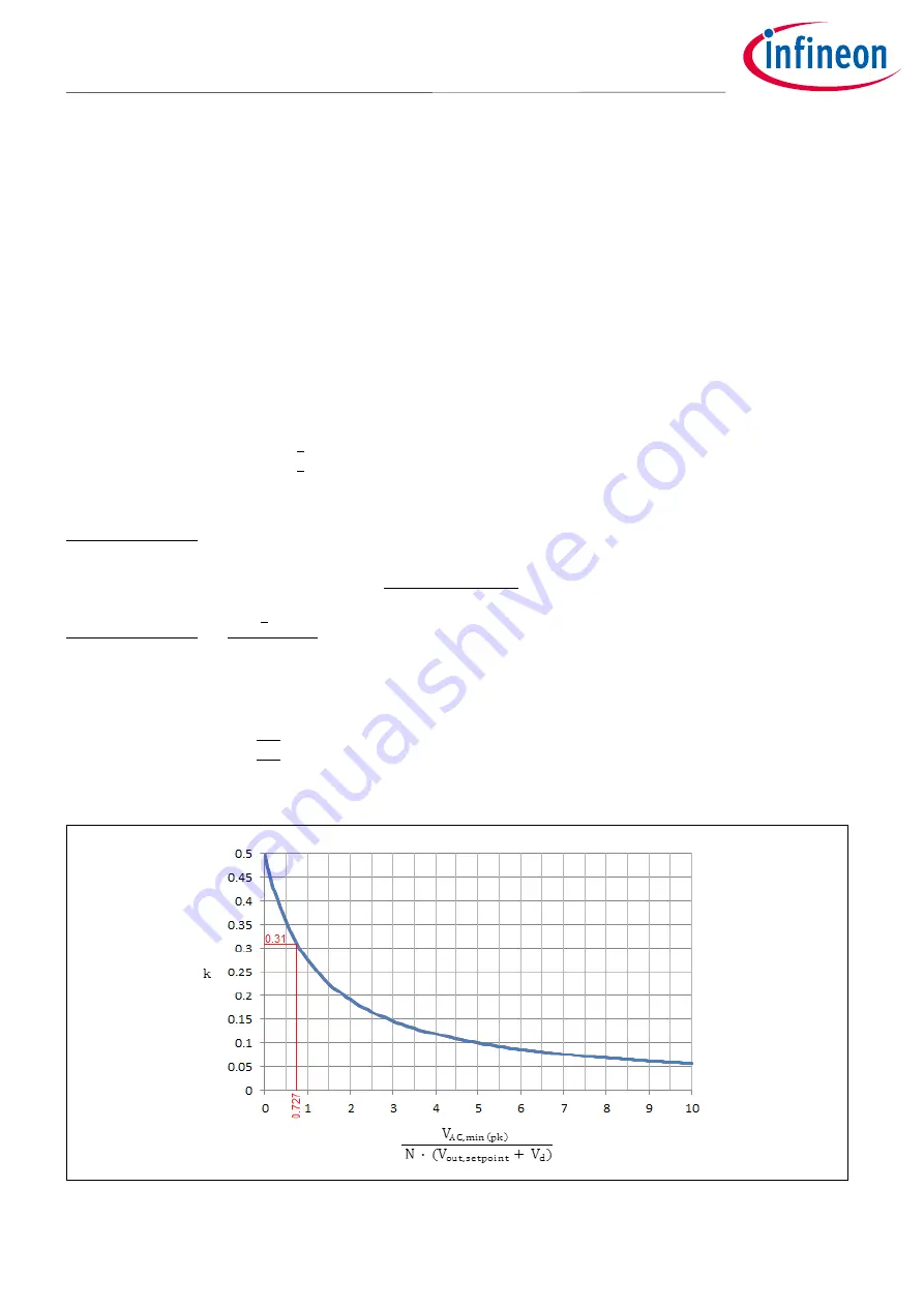
Where k is a number obtained from the function curve in
, based on the variable factor of
𝑉
𝐴𝐶,𝑚𝑖𝑛(𝑝𝑘)
𝑁 ∙ (𝑉
𝑜𝑢𝑡,𝑠𝑒𝑡𝑝𝑜𝑖𝑛𝑡
+ 𝑉
𝑑
)
.
In this design example, the variable factor of
𝑉
𝐴𝐶,𝑚𝑖𝑛(𝑝𝑘)
𝑁 ∙ ( 𝑉
𝑜𝑢𝑡,𝑠𝑒𝑡𝑝𝑜𝑖𝑛𝑡
+ 𝑉
𝑑
)
can be calculated as:
𝑉
𝐴𝐶,𝑚𝑖𝑛(𝑝𝑘)
𝑁 ∙ (𝑉
𝑜𝑢𝑡,𝑠𝑒𝑡𝑝𝑜𝑖𝑛𝑡
+ 𝑉
𝑑
)
=
√2 ∙ 90
3.2 ∙ ( 54 + 0.7)
= 0.727
Referring to the function curve in
, k = 0.31 is obtained.
Based on equation (9), I
pri(rms),max
can then be calculated as:
𝐼
𝑝𝑟𝑖(𝑟𝑚𝑠),𝑚𝑎𝑥
≈ 2.606 ∙ √
0.31
3
𝑰
𝒑𝒓𝒊(𝒓𝒎𝒔),𝒎𝒂𝒙
≈ 𝟎. 𝟖𝟑𝟖 𝑨
Figure 4
Function curve of k


