


Design Guide
15 of 48
V 1.0
2018-06-06
XDPL8218 design guide
For high power factor flyback converter with constant voltage output
VCC capacitance and output UVP design
8
V
CC
capacitance and output UVP design
To fulfill the Energy Star time-to-light requirement of 500 ms, the V
CC
voltage maximum charging time for IC
activation, t
VCCON,charge,max
should not exceed 350 ms. Therefore, the maximum V
CC
capacitance C
VCC,max
can be
defined and calculated as:
𝐶
𝑉𝐶𝐶,𝑚𝑎𝑥
=
𝑉
𝐴𝐶,120(𝑟𝑒𝑐𝑡,𝑎𝑣𝑔)
− 𝑉
𝑉𝐶𝐶𝑂𝑁,𝑚𝑎𝑥
𝑅
𝐻𝑉
∙ 𝑉
𝑉𝐶𝐶𝑂𝑁,𝑚𝑎𝑥
∙ 𝑡
𝑉𝐶𝐶𝑂𝑁,𝑐ℎ𝑎𝑟𝑔𝑒,𝑚𝑎𝑥
∙ [1 −
2
𝜋
∙ 𝑠𝑖𝑛
−1
(
𝑉
𝑉𝐶𝐶𝑂𝑁,𝑚𝑎𝑥
𝑉
𝐴𝐶,120(𝑝𝑘)
)]
(23)
Where V
VCCON,max
is the maximum V
CC
turn-on threshold of 22 V, V
AC,120(rect,avg)
is the average value of rectified 120
V
rms
AC input, and V
AC,120(pk)
is the peak value of 120 V
rms
AC input.
𝐶
𝑉𝐶𝐶,𝑚𝑎𝑥
=
0.9 ∙ 120 − 22
52 ∙ 10
3
∙ 22
∙ 350 ∙ 10
−3
∙ [1 −
2
𝜋
∙ 𝑠𝑖𝑛
−1
(
22
√2 ∙ 120
)] = 24.13 𝜇𝐹
t
start,max
parameter refers to the maximum allowable duration of the start-up phase, which consists of the soft-
start phase and output charging phase. It can be indirectly configured with V
CC
capacitance parameter C
VCC
,
based on:
𝑡
𝑠𝑡𝑎𝑟𝑡,𝑚𝑎𝑥
=
0.8 ∙ 𝐶
𝑉𝐶𝐶
∙ ( 𝑉
𝑉𝐶𝐶𝑂𝑁
− 𝑉
𝑈𝑉𝑂𝐹𝐹
)
𝐼
𝐼𝐶,𝑎𝑣𝑔,𝑒𝑠𝑡
=
0.8 ∙ 𝐶
𝑉𝐶𝐶
∙ (20.5 − 6)
12 ∙ 10
−3
= 967 ∙ 𝐶
𝑉𝐶𝐶
(24)
Where V
VCCON
is the typical V
CC
turn-on voltage threshold of 20.5 V, V
UVOFF
is the typical V
CC
turn-off voltage
threshold of 6 V and I
IC,avg,est
is the estimated IC current consumption of 12 mA.
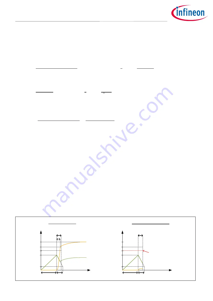
For proper start-up, as shown in
(left)
, C
VCC
has to be high enough to ensure its corresponding t
start,max
calculated from equation (24) is longer than t
out,charge
, whch t
out,charge
is the time needed to charge the output
voltage to the start-up output UVP level V
outUV,start
or higher.
Based on the considerations above, V
CC
capacitor value and IC parameter setting of C
VCC
= 22
𝝁
F are selected in
this design example, which results in t
start,max
= 21.3 ms. In addition, a noise decoupling ceramic capacitor of
C
VCCdecouple
= 0.1
𝝁
F with low ESR is added in parallel to C
VCC
.
In the start-up phase, if the ZCD pin estimated output voltage V
out
is lower than V
outUV,start
over a time-out period
of t
start,max
, the start-up output UVP is triggered. For instance, this could happen if the flyback output is shorted
during the start-up, as shown in
(right)
. It is recommended to configure V
outUV,start
as V
out,start
. Hence,
V
outUV,start
= 27 V is selected in this design example.
The reaction of start-up output UVP is fixed as auto-restart and the auto-restart time is based on the t
auto,restart
parameter. t
auto,restart
= 1.2 sec setting is selected in this design example. Please note that t
auto,restart
is a common
auto-restart time used for other system protections with auto-restart reaction.
time
V
VCC
V
VCCON
V
UVOFF
t
out,charge
(20.5V typ)
(6V typ.)
V
out,start
Output setpoint
t
VCC,holdup
Voltage
V
out
Startup output undervoltage
protection triggered
(V
out
< V
outUV,start
,at t
start,max
)
Normal startup
t
start,max
Output short startup
V
outUV,start
time
V
VCC
V
VCCON
V
UVOFF
(20.5V typ)
(6V typ.)
V
out,start
Output setpoint
t
VCC,holdup
Voltage
t
start,max
V
outUV,start
V
out
t
VCCON,charge
t
VCCON,charge
Figure 10
Normal start-up and start-up output UVP (short) waveforms


