User Manual
4-2
V1.0
TriBoard TC3X6 TH V1.0 and TriBoard TC3X6 V1.0
2019-09
TriBoard Manual TC3X6
Hardware: TriBoard TC3X6 TH V1.0 and TriBoard TC3X6 V1.0
TriBoard Configuration
4.2
Assembly Options
4.2.1
General optional resistors
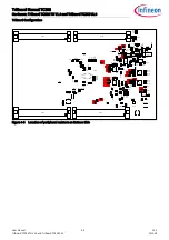
Note:
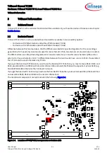
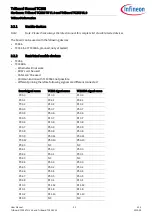
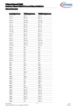
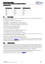
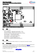
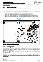
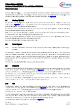
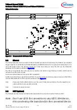
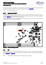
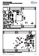
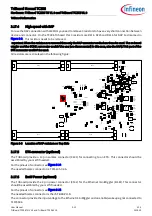
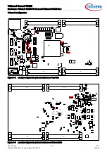
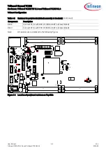
All resistors are red marked in the following figures
Table 4-2
General optional resistors (default assembly in brackets)
Component
Description
R202
Connect P20.2 (/TESTMODE) to GND (not assembled)
R203
XTAL1 Rload (50 Ohm) (not assembled)
R206
XTAL Rparallel (not assembled)
R207
XTAL2 Rserial (assembled)
R238
Switch off EVRC (not assembled)
R240
Switch off EVR33 (not assembled)
R390
Connect V_STBY to toggle LEDs D302...D305 (assembled)
R399
Connect V_UC to toggle LEDs D306...D309 (assembled)
R423
Connect P20.0 with miniWiggler JDS (not assembled)
R424
Connect P20.0 with OCDS1 connector (not assembled)
R425
Connect P21.7 with OCDS1 connector (not assembled)
R426
Connect P20.2 with OCDS1 connector (not assembled)
R427
Connect P21.7 with USR1 of miniWiggler JDS (not assembled)
R428
Connect P20.2 with USR1 of miniWiggler JDS (not assembled)
R429
Connect P21.6 (DAP3) with USR1 of DAP (assembled)
R430
Connect P20.2 with USR1 of DAP (not assembled)
R433
Connect P21.7 with ETK connector (not assembled)
R439
Connect P21.7 with ETK connector (not assembled)
R508
Connect pin MPS of TLF35584 to V_CO (not assembled)
R509
Connect pin MPS of TLF35584 to Ground (assembled)
R524
Connect VDDP3 to V_UC (not assembled)
R525
Connect VDDP3 to +3V3 (not assembled)

