


User Guide
42 of 46
Rev. 1.0
2022-03-09
48V Battery Switch Reference Design
R 48V BATT Switch10
System performance
4.3
Overcurrent detection via shunt resistor
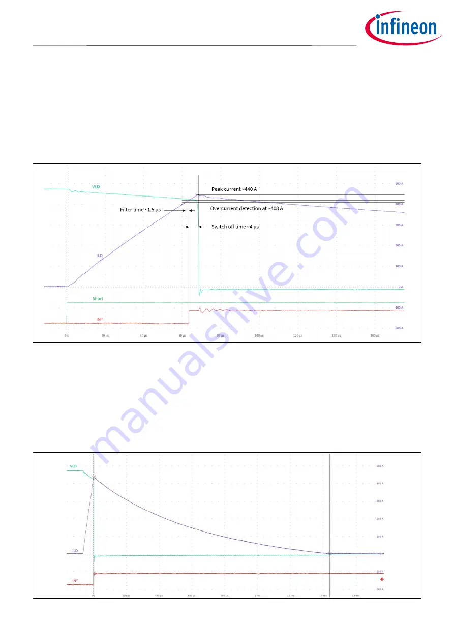
As described in chapter 2.4 “Configuration” the factory setting of the overcurrent shutdown threshold for the
MOSFET gate driver is 413 A typical. Figure 50 shows the waveforms for a short circuit, applied to an activated
switch without load. The green curve marked “Short” shows the trigger for the short circuit switch. When the
short is applied, the load current (violet curve “ILD”) starts to rise linearly. The current slew rate is determined
by the cable inductance. As soon as the overcurrent threshold is reached, the gate driver
2ED4820-EM
generates an interrupt signal (red curve “INT”) and switches off the MOSFETs.
Figure 50
Overcurrent detection – 2ED4820-EM and shunt
Since there is a digital glitch filter time implemented of typically 1.5 µs, the actual overcurrent detection value
is the current value at 1.5 µs before the INT signal goes high, in this case approximately 408 A. Deactivating the
MOSFETS then takes roughly 4 µs. During this time the current continues to rise, which leads to a peak current
of 440 A.
After the deactivation of the MOSFETs the energy stored in the cable inductance between the switch and the
location of the short is dissipated by freewheeling through MOSFET Q13.
Figure 51
Freewheeling after switching off


