


User guide
17 of 24
V1.0
2021-04-15
EVAL-M7-D111T user guide
iMOTION™ evaluation board for smart driver
System design
3
System design
3.1
Schematics
The schematics of the IMD111T control board EVAL-M7-D111T include terminals for digital Hall-feedback inputs
and analog position-feedback inputs. There is an on-board debug circuit on the control board that prompts users
to tune the board via a USB cable. The on-board debug circuit has an isolation function between computer USB
port and IMD111T control board. An optional communication interface on the board is the iMOTION
TM
link
connector (J3). The two resistors R110 and R111 should be removed when using the iMOTION
TM
link debug tool.
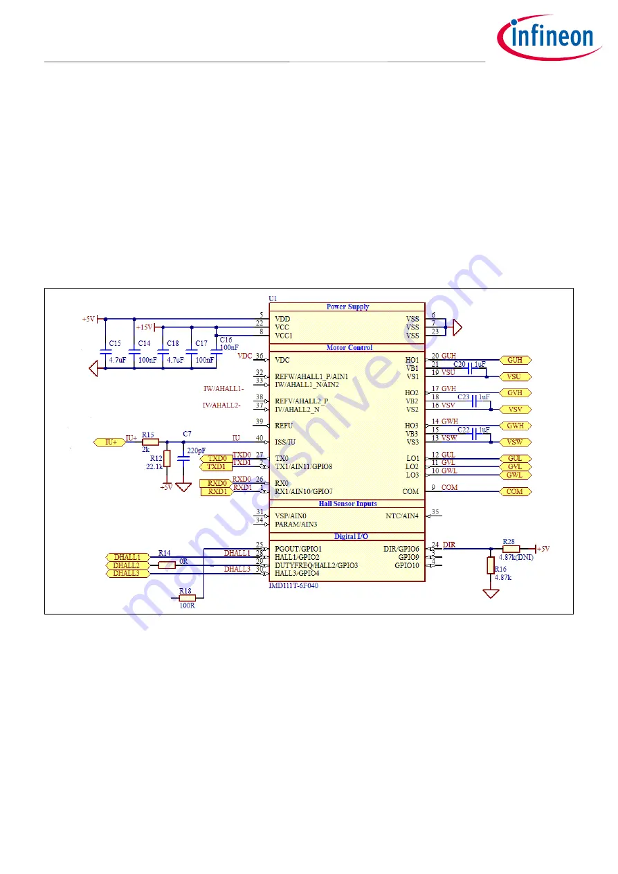
Figure 11 shows the smart driver IMD111T schematics. The complete schematic diagrams are available on the
download section of the Infineon homepage. A log-in is required to download this material.
Figure 11
IMD111T schematics
3.2
Layout
The EVAL-M7-D111T board consists of two copper PCB layers. The copper thickness i
s 35 μm
and the board size
is 70 mm x 5
1 mm. The board material is FR4 grade with 1.6 mm thickness. Check Infineon’s website or contact
Infineon’s technical support team for more detailed information. The Gerber files are available on the download
section of the Infineon homepage. A log-in is required to download this material.
The top layer and bottom layer PCB layout are shown in Figure 12 and Figure 13. For the PCB layout, users should
place the decoupling capacitors as close as possible to the input pins, especially for current-feedback sensing
and bus-voltage sensing input decoupling capacitors.