


User Manual
11
<Revision 1.0>
EVAL-M3-TS6-665PN User Manual
iMOTION™ Modular Application Design Kit
Getting Started with EVAL-M3-TS6-665PN
4
Getting Started with EVAL-M3-TS6-665PN
In order to run the motor system, a combination of the iMOTION™ MADK power board (EVAL-M3-TS6-665PN)
and the matching MADK control board is required. The iMOTION™ Software Tools MCEDesigner and MCEWizard
are also required in order to initialy setup the system, as well as to control and fine-tune the system
performance to match users exact needs. This chapter provides more details on setting up the system and
getting started with iMOTION™ MADK development platform.
4.1
Setting up the system
After downloading and installing the iMOTION™ PC Tools (MCEWizard and MCEDesigner), following steps needs
to be executed in order to run the motor. Refer to user manul for iMOTION™ MADK control board such as (EVAL-
M3-102T), MCEWizard and MCEDesigner documentation for more information.
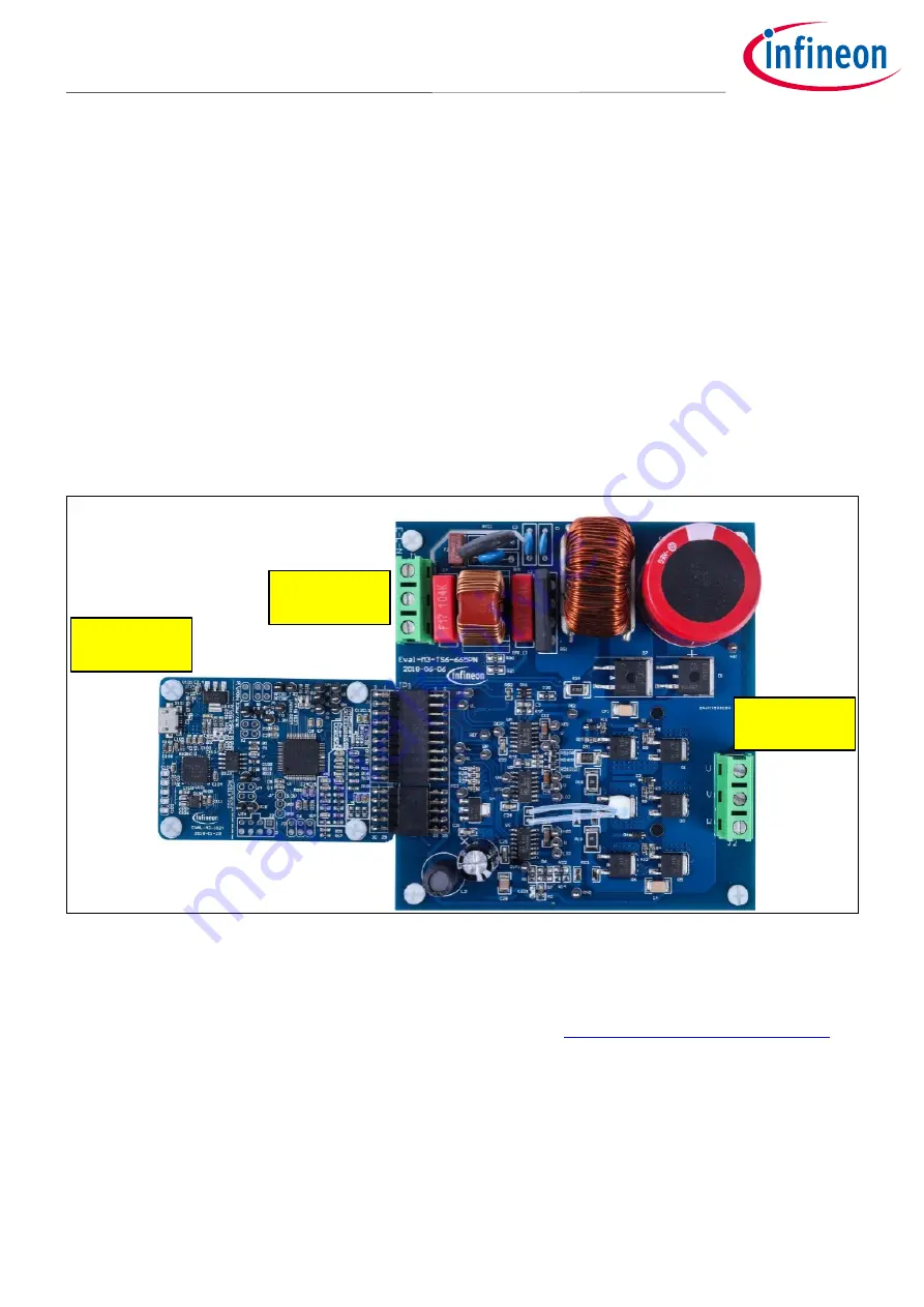
Figure 3 Shows the system connection using EVAL-M3-TS6-665PN and control board (used control board EVAL-
M3-102T for example).
Figure 3
System connection example using EVAL-M3-TS6-665PN and EVAL-M3-102T
1. Connect PC-USB connector on the on-board-debugger to the PC via USB cable.
2. Connect EVAL-M3-TS6-665PN’s MADK M3 30-pin interface connector (J3) to control board (see Figure 3).
3. Get the latest “IMC102T-F064 MCE Software Package” available on
www.infineon.com/imotion-software
web page. (Infineon iMOTION™ control IC IMC102T-F064 is used for control board EVAL-M3-102T).
4. Connect motor phase outputs to the motor.
5. Use MCEWizard to enter the motor and evaluation board hardware parameters and click button “Export to
Designer file (.txt)” to system drive parameters file which will be used by MCEDesigner.
6. Connect AC power to power input connector and power on system.
7. Open MCEDesigner and open MCEDesigner default configuration file (.irc) for IMC102T devices
(IMC102T_xx.irc) by clicking “File” menu and select “Open” in the pull down list.
PC-USB
Connector
AC Power
Input
Motor Phase
Outputs
<201
9
-0
6
-
05
>