User Guide
26 of 35
002-36452 Rev. **
2022-10-07
CYW920819M2EVB-01 evaluation kit user guide
Hardware
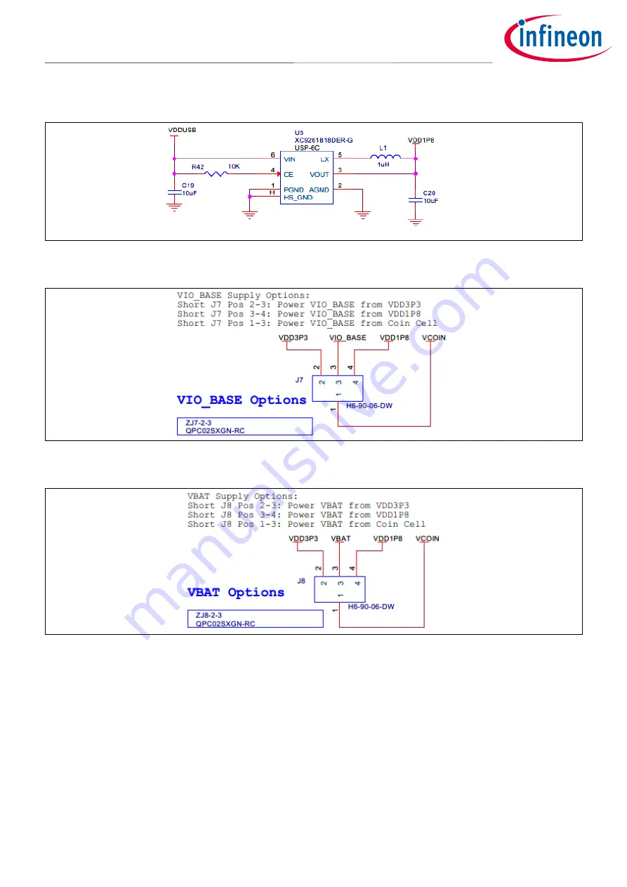
Figure 13
1.8-V regulator circuit
Figure 14
Jumper J7 for VDDIO selection
Figure 15
Jumper J8 for VBAT selection
Page 1: ...eripheral drivers security functions built into ROM allowing application to efficiently use on chip flash 5 dBM Tx output power LE 11 5 dBM Tx output power BR 2 5 dBM Tx output power EDR Serial commun...
Page 2: ...oller Interface I2C Inter Integrated Circuit IDE Integrated Development Environment JTAG Joint Test Action Group LE Low Energy LED Light Emitting Diode LHL Lean High Land LPO Low Power Oscillator MEMS...
Page 3: ...documents Application notes AN225684 Getting started with CYW208XX Describes CYW208XX Bluetooth SoC and how to build your first Bluetooth LE application using the device with ModusToolbox Code example...
Page 4: ...t 10 2 Kit operation 11 2 1 Theory of operation 11 2 2 Jumpers 15 2 3 Buttons and switches 17 2 4 Arduino compatible headers 18 2 5 Other headers 19 2 6 USB serial interface chip 21 2 7 Kit power supp...
Page 5: ...r on devices subjected to high energy discharges Proper ESD precautions are recommended to avoid performance degradation or loss of functionality Store unused CYW920819M2EVB 01 in the protective shipp...
Page 6: ...t compatibility with Arduino shields The development environment is compatible with Windows macOS and Linux operating systems In addition the kit features an onboard programmer debugger KitProg3 The E...
Page 7: ...and Buttons and switches for complete information on DIP switches and jumper settings Do the following before connecting the board and verifying the driver installation 1 Verify that all the jumpers...
Page 8: ...applications for Infineon IoT products Eclipse IDE for ModusToolbox is a multi platform integrated development environment IDE used to create new applications update application code change middleware...
Page 9: ...ese code examples are compatible with this kit You can either browse the collection of starter applications during application set up through File New ModusToolbox Application or browse the collection...
Page 10: ...Help Eclipse IDE for ModusToolbox Documentation Quick Start Guide This guide gives you the basics for using ModusToolbox ModusToolbox General Documentation Choose Help ModusToolbox General Documentati...
Page 11: ...s This chapter introduces you to CYW920819M2EVB 01 and the features that will be used as part of the kit operation This chapter also discusses features such as the Bluetooth connectivity and programmi...
Page 12: ...wer supply options Digital MIC Buttons 1 Recovery 2 Reset 3 User User LED Carrier VBAT VDDIO and VDDUSB Monitoring Analog MIC Ambient Light Sensor Thermistor Infineon Bluetooth Bluetooth LE chip 32 76...
Page 13: ...ermistor analog mic and real time clock by disabling VDDP 2 VIO_BASE select jumper J7 This jumper is used to select the VIO_BASE power source Possible selections are 3 0 V 1 8 V or VCOIN which is the...
Page 14: ...can occur 14 Recovery button SW1 This button is used to put the device in recovery mode To put the device in recovery mode press and hold the recovery button press and release the reset button and the...
Page 15: ...ty of devices CYW20819 device and USB Serial IC with different high level and low level voltages for input and output operations 34 VDDIO current measurement jumper J17 This jumper is used to power th...
Page 16: ...consumption of VBATT when using 1 8 V supply 1 and 3 Open Short these pins to use the coin cell supply VBATT of the CYW20819 device Also use this jumper to measure the current consumption of VBATT whe...
Page 17: ...detector to shut down the chip when supply voltage VBATT drops below the operating range The shutdown voltage VSHUT lies between a minimum of 1 5 V and a maximum of 1 7 V See the datasheet for more de...
Page 18: ...he debug header if the slide switch is in the ON state ON P3 Connects P3 to the Arduino compatible header pin ARD_D45SWDIO if the slide switch is in the OFF state Connects P3 to the debug header if th...
Page 19: ...V supply output to the Arduino Shield 6 GND GND Ground 7 GND GND Ground 8 NC NC NC Table 16 Header J2 pin configuration Header J2 Arduino pin Connection on CYW20819 WICED Enum name Description 1 A0 P8...
Page 20: ...VD_8 NC Ambient light sensor INT 9 RSVD_9 P11 WICED_P11 SPI Slave select external flash memory 10 VIO_BASE NC J13 is a 10 pin debugger header to debug CYW920819M2EVB 01 using SWD Table 19 Header J13 p...
Page 21: ...to power the always ON GPIO pins VBAT to power the core The total current consumption by the device is the sum of the current consumed by the VIO_BASE and VBAT power domains To measure the current con...
Page 22: ...e CYW20819 device can be multiplexed to various peripherals For more information on the peripherals that can be routed to the various GPIOs see the device datasheet For this board the ModusToolbox sof...
Page 23: ...s etched on the carrier module PCB UART signals and GPIOs are brought out to module pins to interface with the baseboard 3 1 1 CYW20819 The CYW920819M2EVB 01 board employs the CYW20819A1KFBG device wh...
Page 24: ...w control mechanism provided by the PUART Note For applications involving low power modes the CYW920819M2EVB 01 evaluation board needs to be reset after plugging it into the computer This is due to th...
Page 25: ...ll up resistors for the I2 C lines to the ambient light sensor i e SCL and SDA Note that J19 PERIPH ENABLE should be shorted for any I2 C devices to be connected because the pull up voltages for SCL a...
Page 26: ...Guide 26 of 35 002 36452 Rev 2022 10 07 CYW920819M2EVB 01 evaluation kit user guide Hardware Figure 13 1 8 V regulator circuit Figure 14 Jumper J7 for VDDIO selection Figure 15 Jumper J8 for VBAT sele...
Page 27: ...ircuit in the carrier module In the default configuration of R40 shown below position A C the reset button is routed to the Arduino compatible header reset pin in addition to the device so both the de...
Page 28: ...uration Figure 19 Reset to Arduino compatible header Figure 20 P1 to ARD_RST_N R13 resistor 3 6 Thermistor The thermistor circuit is a simple voltage divider circuit consisting of an NTC thermistor th...
Page 29: ...ver should configure the respective pins in the user application in order to use the onboard serial flash Figure 22 External serial flash 3 8 Ambient light sensor CYW920819M2EVB 01 has an onboard ligh...
Page 30: ...kspace Explorer in Eclipse IDE for ModusToolbox after you create an application for this kit install libraries bt_sdk version components BT SDK 208XX A1_Bluetooth platforms CYW920819M2EVB_01 wiced_pla...
Page 31: ...VPA_BASE VPA_BT J16 3 5 BT_USB_DN NC J21 2 6 LED_1L P29 SW4 2 J11 2 WICED_P29 7 GND GND Ground 8 ARD_A4 P12 J2 5 WICED_P12 9 ARD_D13 P9 J3 5 WICED_P09 10 ARD_A5 P13 J2 6 WICED_P13 11 ARD_D8 P14 J3 10...
Page 32: ...LPO EXT_LPO NC 51 GND GND Ground 52 ARD_RST_N P1 R40 B WICED_01 53 MIC_BIAS NC 54 BT_RST_N RST_N SW2 3 4 RESET_ BTN J13 10 U12 3 55 MIC_AVDD NC VIO_BASE 56 RSVD_9 P11 U11 1 J12 9 WICED_P11 57 GND GND...
Page 33: ...19M2EVB 01 evaluation kit user guide CYW20819 device I O mapping Carrier module pin Carrier module pin name CYW20819 pin Baseboard connection 1 Baseboard connection 2 Baseboard connection 3 WICED Enum...
Page 34: ...User Guide 34 of 35 002 36452 Rev 2022 10 07 CYW920819M2EVB 01 evaluation kit user guide Revision history Revision history Date Version Description 2022 10 07 Initial release...
Page 35: ...ustomer s applications The data contained in this document is exclusively intended for technically trained staff It is the responsibility of customer s technical departments to evaluate the suitabilit...