

Caution
Vacuum component
Dirt and damages impair the function of the
vacuum component.
When handling vacuum components, take ap-
propriate measures to ensure cleanliness and
prevent damages.
Caution
Dirt sensitive area
Touching the product or parts thereof with bare
hands increases the desorption rate.
Always wear clean, lint-free gloves and use
clean tools when working in this area.
Precondition
•
Gauge removed from vacuum system
Tools required
•
Allen wrench AF 3
•
Open-end wrench AF 7
•
Pliers for circlip
•
Polishing cloth (grain 400) or Scotch-Brite
•
Tweezers
•
Mounting tool for ignition aid
•
Cleaning alcohol
Disassembling the Gauge
(MAG050
Figure 1, MAG060
Precondition
•
Gauge removed from vacuum system
Procedure
Unfasten the hex head screw (3) on the magnet unit (4)
and remove the magnet unit.
The magnetic force and the tendency to tilt
make it more difficult to separate the magnet
unit and the measuring chamber (7).
For reasons of tolerance, the same magnet
unit has to be used again when reassembling
the gauge.
Remove the circlip (5) and the pole insert (6) from the
measuring chamber (7).
Loosen the 2 hex socket screws (1a) and remove the
coaxial connector (2a).
Remove the 4 (or 2) hex socket screws (8) incl. the
lock washers (8a) on the back of the measuring cham-
ber (7).
MAG050:
Carefully remove the following items in this
order: pressure piece (9), complete anode (10), inner
ring (11) and FPM seal (12).
MAG060:
Carefully remove the following items in this
order: pressure piece (9), washer (10b), complete
anode (10), metal seal (11) and centering ring (12).
The parts can now be cleaned or replaced individually
(
→
next section).
Cleaning the Gauge
Procedure
DANGER
Adhere to the relevant regulations and take the necessary
precautions when handling and disposing of cleaning
agents.
Cleaning the measuring chamber and the pole insert:
Clean the inside walls of the measuring chamber and
the pole insert to a bright finish. Use a polishing cloth.
Caution
Sealing surfaces must only be worked concentrically.
Rinse the measuring chamber and the pole insert with
alcohol.
Dry both.
Cleaning or replacing the anode (10):
Remove the old ignition aid (10a), for example with
tweezers.
Rub the anode pin to a bright finish by means of a
polishing cloth.
Caution
Do not bend the anode.
Do not carry out mechanical work on the ceramic
part.
Rinse the anode with cleaning alcohol.
Dry the anode.
Insert the new ignition aid (10a) into the mounting tool.
Carefully press the anode (cleaned or new) centered
and parallel to the tool axis into the ignition aid and in-
sert it to a depth of
≈
15 mm. The final position is estab-
lished only after the anode is installed.
Assembling the Gauge
Procedure
MAG050:
Insert the FPM seal (12) with the inner
ring (11) centered into the measuring chamber (7).
Sealing surface, seal and ceramic part must be clean
(
→
figure 1).
MAG060:
Insert new metal seal (11) with the centering
ring (12) centered into the measuring chamber (7).
Sealing surface, seal and ceramic part must be clean
(
→
figure 2).
Carefully insert the anode (10) incl. ignition aid (10a)
into the measuring chamber.
Place the pressure piece (9) incl. Washer (10b) on the
measuring chamber (7) and tighten the screws (8) incl.
lock washers (8a) uniformly until the stop position is
reached.
Position the ignition aid (10a): slide the mounting tool
over the anode pin until the mechanical stop is
reached.
Remove particles in the measuring chamber (7) by
blowing with dry nitrogen (while the flange of the
measuring chamber is pointing downward).
Slide the pole insert (6) into the measuring chamber (7)
up to the mechanical stop (MAG050
MAG060
Place the circlip (5) snugly fitting on the pole insert.
Visually check that the anode pin is centered
over the hole of the pole insert (tolerated ec-
centricity
≤0.5 mm).
If possible perform a leak test
(leak rate <10
-
9
hPa l/s
│mbar l/s).
Place the coaxial connector (2a) on the measuring
chamber and tighten both hex socket screws (1a).
Mount the magnet unit (4) and lock it with the
screw (3).
Figure 1:
MAG050
Figure 2:
MAG060
Troubleshooting
Problem
Possible cause
Correction
The measurement
values indicated
are too low
Gauge contaminated
Clean the gauge
Spare Parts / Accessories
When ordering spare parts, always indicate:
•
all information on the nameplate
•
description and ordering number according to spare parts
list
MAG050
Position
→
figure 1
Ordering
number
Maintenance kit
Inner ring
O-ring FPM, 3.69×1.78
O-ring FPM, 10.82×1.78
Ignition aid
(11)
—
1)
(12)
(10a)
BN 846 239-T
Repair kit
O-ring FPM, 10.82×1.78
Anode complete
Inner ring
Ignition aid
(12)
(10)
(11)
(10a)
BN 846 252-T
1)
O-ring not used.
MAG060
Position
→
figure 2
Ordering
number
Maintenance kit
Metal seal, HNV100 9×1.6
Centering ring
Ignition aid
Washer
(11)
(12)
(10a)
(10b)
BN 846 241-T
Repair kit
Anode complete
Washer
Metal seal, HNV100 9×1.6
Centering ring
Ignition aid
(10)
(10b)
(11)
(12)
(10a)
BN 846 240-T
Returning the Product
Forwarding contaminated products
Contaminated products (e.g. radioactive, toxic,
caustic or microbiological hazard) can be detri-
mental to health and environment.
Products returned to INFICON should preferably
be free of harmful substances. Adhere to the
forwarding regulations of all involved countries
and forwarding companies and enclose a duly
completed declaration of contamination (form
under www.inficon.com).
Products that are not clearly declared as "free of harmful
substances" are decontaminated at the expense of the
customer.
Products not accompanied by a duly completed declaration
of contamination are returned to the sender at his own ex-
pense.
Disposal
Contaminated parts
Contaminated parts can be detrimental to health
and environment.
Before beginning to work, find out whether any
parts are contaminated. Adhere to the relevant
regulations and take the necessary precautions
when handling contaminated parts.
Substances detrimental to the environment
Products or parts thereof (mechanical and elec-
tric components, operating fluids etc.) can be de-
trimental to the environment.
Dispose of such substances in accordance with
the relevant local regulations.
Separating the components
After disassembling the product, separate its components
according to the following criteria:
•
Contaminated components
Contaminated components (radioactive, toxic, caustic, or
biological hazard etc.) must be decontaminated in accord-
ance with the relevant national regulations, separated
according to their materials, and recycled.
•
Other components
Such components must be separated according to their
materials and recycled.
Appendix
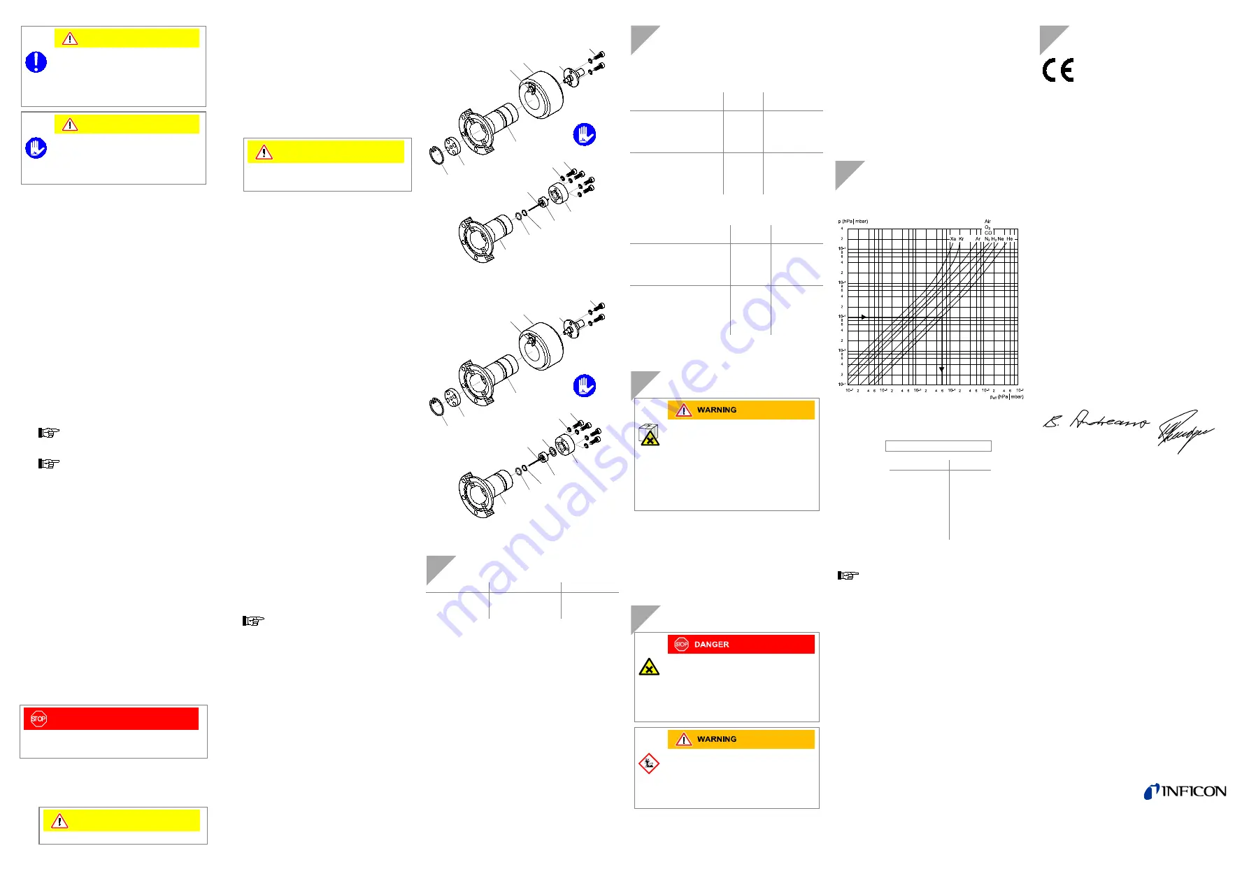
Gas Type Dependence
Indicated pressure (gauge calibrated for air)
In the range below 10
-
5
hPa
│mbar the pressure indication is
linear. For gases other than air the pressure can be deter-
mined by means of a simple conversion formula:
p
eff
= C × displayed pressure
where
Gas type
C
Air (N
2
, O
2
, CO)
1.0
Xe
0.4
Kr
0.5
Ar
0.8
H
2
2.4
Ne
4.1
He
5.9
These conversion factors are average values.
A mixture of gases and vapors is often involved. In
this case accurate determination is only possible
with a partial pressure measuring instrument, e.g.
an INFICON quadrupole mass spectrometer.
Literature
[1] www.inficon.com
Operating Manual
VGC083C
tinb42e1
INFICON AG, LI-0496 Balzers, Liechtenstein
EU Declaration of Conformity
We, INFICON, hereby declare that the equip-
ment mentioned below comply with the pro-
visions of the following directives:
•
2014/30/EU, OJ L 96/79, 29.3.2014
(EMC Directive; directive relating to electro-
magnetic compatibility)
•
2011/65/EU, OJ L 174/88, 1.7.2011
(RoHS Directive; directive on the restriction of
the use of certain hazardous substances in
electrical and electronic equipment)
Products
Cold Cathode Gauge
MAG050
MAG060
(operation with VGC083C)
Standards
Harmonized and international/national standards and specifi-
cations:
•
EN 61000-6-2:2005
(EMC: generic immunity standard)
•
EN 61000-6-4:2007 + A1:2011
(EMC: generic emission standard)
•
EN 61010-1:2010
(Safety requirements for electrical equipment for measure-
ment, control and laboratory use)
•
EN 61326-1:2013; Group 1, Class A
(EMC requirements for electrical equipment for measure-
ment, control and laboratory use)
Manufacturer / Signatures
INFICON AG, Alte Landstraße 6, LI-9496 Balzers
15 June 2018
15 June 2018
Dr. Bernhard Andreaus
Director Product Evolution
Markus Truniger
Product Manager
10
9
8
7
8a
10a
11
12
3
5
1a
4
2a
7
6
10
9
8
8a
10a
11
12
7
10b
3
5
1a
4
2a
7
6
LI–9496 Balzers
Liechtenstein
Tel +423 / 388 3111
Fax +423 / 388 3700
[email protected]
www.inficon.com