23
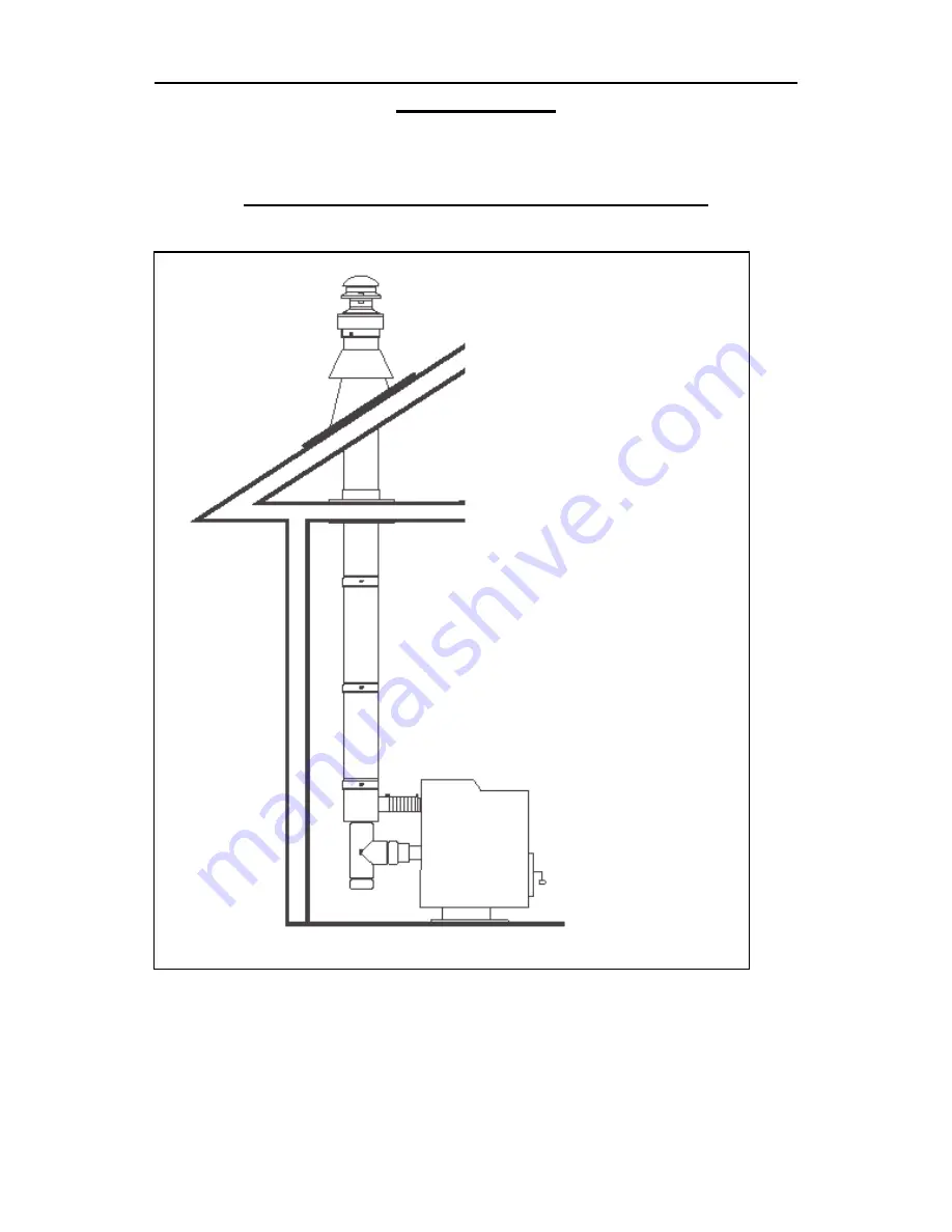
SELKIRK DIRECT-TEMP VENT SYSTEM FOR PELLET
APPLIANCES
Images courtesy of Selkirk
THROUGH THE ROOF VERTICAL TERMINATION KIT
Figure 14
Page 1: ...entire manual before installation and use of this pellet fuel burning room heater Failure to follow these instructions could result in property damage bodily injury or even death Contact your local b...
Page 2: ...ns 8 11 Thermostat Installation 12 Clearances to Combustibles 13 14 Installing Your Room Heater 15 23 Mobile Home Installations 24 Insert Pellet Stove 25 27 Vent Termination Locations 28 Maintenance 2...
Page 3: ...um grade 3 maximum Standard grade Moisture Content 8 maximum Heat Content minimum 8 200 btu hr It is important to note that the ash content of the fuel and frequency of operation determine the frequen...
Page 4: ...utside combustion air source It is recommended that the exhaust vent be cleaned bi annually or after every two tons of pellets Soot or creosote may accumulate when the stove is operated under incorrec...
Page 5: ...restrictions or inspection requirements in your area Notify your insurance company of your new stove Allow the stove to cool before performing any maintenance Ashes must be disposed of in a metal cont...
Page 6: ...6 SPECIFICATIONS Heating Specifications Burn Rate 40 000 btu hr or 4 8 lbs of fuel per hour Hopper Capacity 50 lbs Depends on quality and heating value of pellet fuel DIMENSIONS Figure 1...
Page 7: ...7 DIMENSIONS The minimum installation dimensions of the insert opening are 32 813 mm wide x 22 3 4 578 mm high x 12 1 4 311 mm deep Figure 2...
Page 8: ...tove switch it to manual mode so you can have full control of the pellet stoves control board functions and familiarize yourself with how the pellet stove works It is in this mode that the heat level...
Page 9: ...ay do so by pressing the FAN button If the flame goes out or the heat output is too high on minimum heat level setting use the AUGER TRIM button to make adjustments See the AUGER TRIM button descripti...
Page 10: ...nto the burn pot The electric ignition system will be automatically activated flames in the burn pot will normally appear between 3 7 minutes Once the flame has been established the start up cycle wil...
Page 11: ...actory setting and works for most types of fuel Figure 3 Control Panel Open Door If the door is opened while the unit is operating it must be closed within 30 seconds or the unit will go into vacuum e...
Page 12: ...t Disconnect unit from power supply Open right side panel to gain access to rear of control panel Take the thermostat wires and connect to the green screw terminal on the rear of the control panel see...
Page 13: ...on a combustible floor a 1 2 thick non combustible hearth pad must be installed under the unit The pad must extend at least the width of the appliance and at least the depth of the appliance plus 6 15...
Page 14: ...if its dimensions fall within the chart below Mantle Depth Mantle Height from Floor 10 254 mm 40 1016 mm 8 7 8 222 mm 39 991 mm 7 13 16 197 mm 38 965 mm 6 11 16 171 mm 37 940 mm 5 5 8 143 mm 36 914 m...
Page 15: ...imney The chimney must be lined if over 6 150 mm in diameter or if it has a cross sectional area of over 28 square inches Venting can pass through the ceiling and roof if listed pipe is used Do not ob...
Page 16: ...re that the outside air vent has a proper cap on it to prevent rodents from entering and also is installed where it won t become blocked with snow etc 8 Connect the exhaust vent pipe to the exhaust ou...
Page 17: ...17 HORIZONTAL EXHAUST VENT INSTALLATION continued Figure 8 Figure 9...
Page 18: ...t on your exterior wall and cut a hole 2 1 2 64 mm in diameter through the wall 5 Secure all vent joint connections with 3 screws Seal the exhaust vent joint connections with high temperature silicone...
Page 19: ...exhaust vent through the wall be sure to make sure that 3 75 mm clearances to combustibles are maintained 5 Secure all vent joint connections with 3 screws Seal the exhaust vent joint connections wit...
Page 20: ...20 SELKIRK DIRECT TEMP VENT SYSTEM FOR PELLET APPLIANCES Images courtesy of Selkirk...
Page 21: ...21 SELKIRK DIRECT TEMP VENT SYSTEM FOR PELLET APPLIANCES Images courtesy of Selkirk UP OUT HORIZONTAL TERMINATION KIT Figure 12...
Page 22: ...22 SELKIRK DIRECT TEMP VENT SYSTEM FOR PELLET APPLIANCES Images courtesy of Selkirk STRAIGHT OUT HORIZONTAL TERMINATION KIT Figure 13...
Page 23: ...23 SELKIRK DIRECT TEMP VENT SYSTEM FOR PELLET APPLIANCES Images courtesy of Selkirk THROUGH THE ROOF VERTICAL TERMINATION KIT Figure 14...
Page 24: ...sure that the unit is permanently electrically grounded to the chassis of your home IT IS MANDATORY TO TAKE THE COMBUSTION AIR FROM THE OUTSIDE WHEN INSTALLING THIS UNIT IN AIR TIGHT OR MANUFACTURED M...
Page 25: ...e shroud must be installed before unit is set into its final position Step 1 Shroud Side Facing the back of the unit take the left shroud side piece no control panel hole and fasten as shown with 2 sc...
Page 26: ...e the top shroud side piece and fasten as shown with 4 screws provided Step 4 Control Board Take the control board and insert it from the back of the right shroud side facing front of unit Fasten cont...
Page 27: ...xhaust fan and the either a 90 elbow or a clean out tee with cap The air intake can be attached to the appliance by using a hose clamp 6 Connect the stove to the coupling on the bottom of the exhaust...
Page 28: ...F 12 30 cm To outside corner G 12 30 cm To inside corner combustible wall H 3 91 cm within a height of 15 4 5 m above the meter regulator assembly To each side of center line extended above natural g...
Page 29: ...rn pot Inspect the burn pot regularly to check that the holes have not become plugged If necessary clean thoroughly It is imperative that the burn pot be re installed the correct way or the unit will...
Page 30: ...r shop vac may have a special filter or bag available to eliminate this leakage 5 Remove ash pan and dispose of ashes into metal container 6 Reinstall ash pan 7 Reinstall burn pot and burn pot liner A...
Page 31: ...ONNECT POWER BEFORE SERVICING UNIT Over time ash or dust may accumulate on the blades of the convection combustion fans The fans should be inspected periodically and if any accumulation is present vac...
Page 32: ...d To clean the chimney detach the vent where it attaches to the combustion blower If creosote has accumulated it should be removed Inspect the entire vent system from unit exhaust to termination Creos...
Page 33: ...an optional firebox decorative liner as well as a ceramic log set Decorative Liner Installation 1 Install the center panel be sure to line up the hole with the drop tube 2 Install the left and right p...
Page 34: ...m in the firebox Check the vacuum switch by shorting out the vacuum switch then turn the control panel to OFF and back to ON If the unit starts to operate change the vacuum switch Check the exhaust te...
Page 35: ...r if none check circuit board fuse Ensure the exhaust blower is operating Check the vacuum hose is connected or damaged Bypass the vacuum switch by placing a jumper wire on the two electrical connecti...
Page 36: ...burn pot liner be sure to follow instructions for disposal of ashes found on page 30 Circuit board malfunction Time the fuel feed light at each setting after the stove has completed the initial Start...
Page 37: ...37 WIRING DIAGRAM...
Page 38: ...iding the Warranty Item Part control panel circuit board DHC3000 REV DSVH3001 auger motor 250 F normally open high limit snap disc 611240 140 F normally open exhaust temperature snap disc X 2269F conv...
Page 39: ...rized Inca Metal dealer and is subject to the following conditions and limitations This factory warranty is nontransferable and may not be extended whatsoever by any of our representatives A licensed...
Page 40: ...h respect to this product its components or accessories are excluded Inca Metal neither assumes nor authorizes any third party to assume on its behalf any other liabilities with respect to the sale of...