


VST
X
User Manual
Revision
2.
3
35
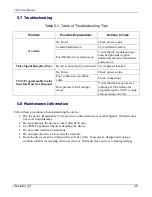
4.4.2
Video Input (Connector Housing)
Connect a Composite video source to the video input.
4.4.3
Audio Input (Connector Housing)
Connect audio sources to the two analog audio line inputs.
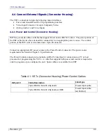
Table 4-3: VSTx (Connector Housing) Audio Pinout
Pin
Function
Notes
1
LINE SELECT
Not Active
2
+5V MIC BIAS
3
AUDIO IN
Audio line input.
4
GROUND
Connected internally to signal & chassis ground
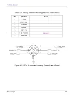
Figure 4-8: VSTx (Connector Housing) Audio Detail
4.5
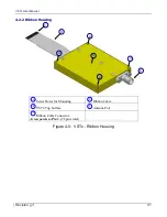
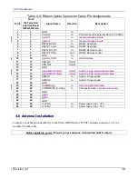
Connect External Signals (Ribbon Housing)
For best grounding, the VST
X
ribbon cable should be connected to an interface that terminates all the
signals. (Do not attempt to split the cable or use multiple connectors on the end of the ribbon).
To terminate the VST
X
ribbon cable, you may use an interface board which is available from IMT, or
the following connector: Hirose Electronics Model Number FH33-26s-0.6sh(10)
When planning your system grounding scheme, provide both power and ground to the VST
X
ribbon
cable from a PCB mounted connector. Follow appropriate grounding methods in your system to
facilitate good EMC, including use of a single point of origin for grounds.
See Section 5 “Operation” for additional detail on the ribbon cable pins and their usage.
Summary of Contents for VSTx
Page 1: ...VSTX HD SD COFDM Transmitter User Manual IMT PUBLICATION M22 0002 00A REV 2 3...
Page 12: ...VSTX User Manual Revision 2 3 12...
Page 13: ...VSTX User Manual Revision 2 3 13 Chapter One 1 Introduction...
Page 15: ...VSTX User Manual Revision 2 3 15 Chapter Two 2 Description...
Page 22: ...VSTX User Manual Revision 2 3 22...
Page 23: ...VSTX User Manual Revision 2 3 23 Chapter Three 3 Specifications...
Page 27: ...VSTX User Manual Revision 2 3 27 Chapter Four 4 Installation...
Page 37: ...VSTX User Manual Revision 2 3 37 Chapter Five 5 Operation...
Page 46: ...VSTX User Manual Revision 2 3 46...


