


5 - 12
99906549 rev 00 (JANUARY-2020)
SECTION 5: MAINTENANCE
IOWA MOLD TOOLING CO., INC.
(641) 923-3711
CAS40PL, CAS40PL-CW, CAS40PLE, CAS40PLE-CW
5.4.1, Removing Panels for Machine Mainte-
nance Access
to remove the drive assembly ac-
cess side panel.
Hoses and wires are routed away from potential
pinch points, heat sources, and other hazards.
However, when service is performed on a ma-
chine, it can become necessary to cut zip ties,
which can allow hoses and wires to become ex-
posed to some hazards within the enclosure. Ver-
ify that no hoses or wires are near fan blades,
sharp edges, or other pinch points.
Hoses and wires should perform for the service
life of the product. Occasionally, a plug or hose
end may work itself loose over time. Check all the
hose
fi
ttings to see that there is no visible leak-
age.
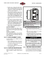
5.5 SERVICING THE SYSTEM
FUSE
DANGER
The system fuse will need to be replaced if
blown when tripped. When changing a fuse, or
dealing directly with any function of the electri-
cal system maintenance, always be aware of the
safety warnings given in Section 1, Safety.
WARNING
Before performing maintenance:
Shut down machine, relieve all system pres-
sure and lock out all power, as per the Safety
Section of this manual.
NOTE THAT THE SYSTEM CAN BE STARTED
REMOTELY:
Always clearly tag the start-up instrumentation
against accidental system start-ups during
maintenance.
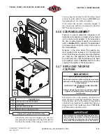
To access the machine area where the fuse is
located, the long-side canopy panel must be re-
moved. Consult
Section 5.4.1, Removing Pan-
els for Machine Maintenance Access
to re-
move the drive assembly-side access side panel.
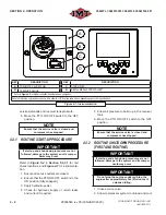
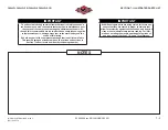
Consult
Figure 5-7
. for the locations of the fuse.
IMT
®
recommends using a fuse removal tool,
though pliers will su
ffi
ce, when removing the fuse.
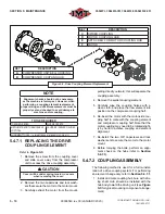
5.6 PRESSURE
(SAFETY)
RELIEF VALVES
Refer to
Figure 5-8
. Although the pressure (safe-
ty) relief valves have a reset ring at the cap,
DO
NOT
test the valves by pulling on their reset rings.
The pressure relief valves require no safety test-
ing. Should one prove faulty per indications given
in the
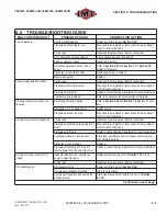
Troubleshooting Guide (Section 6.2)
, re-
place the valve.
C
A
B
D
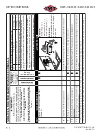
Figure 5-7: Fuse and Relay Locations
KEY
DESCRIPTION
A
RELAY
B
HYDRAULIC MOTOR (reference)
C
FUSE, 10A
D
JCASE FUSE, 30A
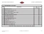
Summary of Contents for CAS40PL
Page 2: ...BLANK PAGE...
Page 81: ...BLANK PAGE...


