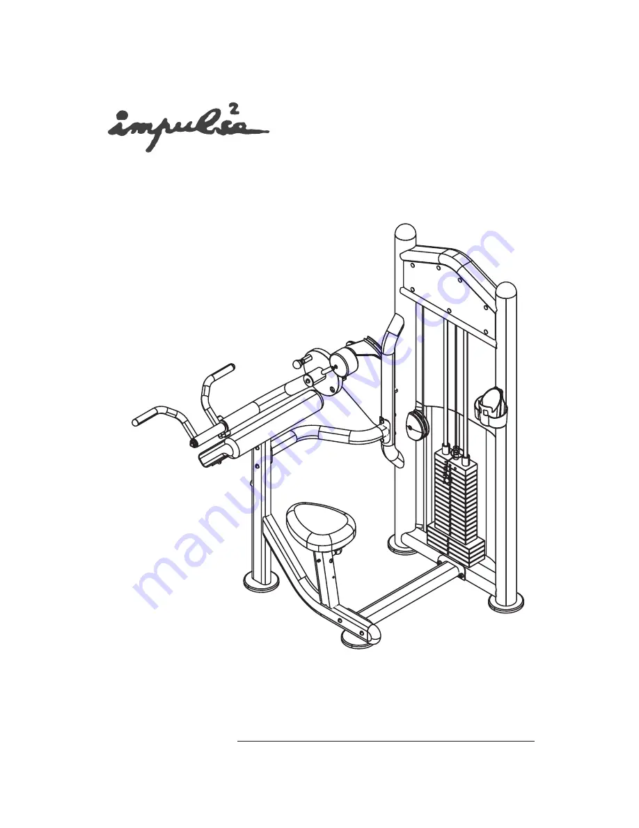
I
A r m C u r l
A s s e m b l y I n s t r u c t i o n s
T 8 0 0 3
Page 1: ...I Arm Curl Assembly Instructions T8003 ...
Page 2: ...Table of contents Important Safety Instructions 1 Exploded View Diagram 2 Hardware List 3 Parts List 4 Assembly instructions 5 ...
Page 3: ...rop or insert anything into any opening in the equipment Always check the unit and its cables before each use Make sure that all fasteners and cables are secure and in good working condition Frayed or worn cables can be dangerous and may cause injury Periodically check these cables for any indication of wear Keep hands limbs loose clothing and long hair well out of the way of moving parts Do not a...
Page 4: ...2 I Arm Curl Exploded View Diagram T8003 ...
Page 5: ...3 Hardware List 0 100 10 20 30 40 50 60 70 80 90 110 120 130 140 150 Inches 0 1 2 3 4 5 6 12 14 34 34 34 34 34 34 14 14 14 14 14 12 12 12 12 12 Millimeters ...
Page 6: ...ulley D End Cap Rear Side Cover Front Side Cover Plastic Block Adj foot Plate Grip Aluminium Plug Weight Rubber Bumper RT Plug Slide Sleeve Button Long Pop Pin Key 5Lbs Weight 10Lbs Weight 15Lbs Weight Top Plate Φ Φ Weight Pin Bearing ID 25 Cable Bumpper Bronze Bushing ID 25 4 Allen Bolt M12 40 Allen Bolt M10 115 Allen Bolt M10 80 Allen Bolt M10 70 Allen Bolt M10 45 Allen Bolt M10 35 Allen Bolt M1...
Page 7: ...ponents may be large heavy or awkward to handle alone It is important that you asse mble your product in a clean clear uncluttered area This will enable you to move around the product while you are fitting com onents and reduce the possibility of injury during assembly As with any assembled part proper alignment and adjustment is critical While tightening the fasteners be sure to leave room for ad...
Page 8: ...Step1 Install the Adj Foot Plates Align the Adj Foot Plates 28 to the Main Upright 1 and the Seat Support 3 then secure them by hands 6 ...
Page 9: ...pright 1 using 2 Attach the Seat Support 3 to the Low Cross 2 and the Upper Cross 4 using two Allen Bolts 48 M10 115 two Allen Bolts 49 M10 80 four Nylon Locknuts 62 M10 eight Washers 60 11 20 1 5 four Allen Bolts 50 M10 70 four Nylon Locknuts 62 M10 eight Washers 60 11 20 1 5 Φ Φ Φ Φ 7 ...
Page 10: ...8 Step3 Assemble The Pillow Block Attach the Pillow Block 20 to the Main Upright 1 using two Allen Bolts 47 M12 40 four Washers 59 13 24 1 5 two Nylon Locknuts 61 M12 Φ Φ two Spacer 86 ...
Page 11: ...tep4 Assemble The Arm 1 Insert the Arm 6 into the Main Upright 1 and thro ugh the Pillow Block 20 2 Attach the Counter Poise Block 19 to the Arm 6 using two two Shoulder Bolt 54 M8 25 Φ Spring Washer 64 8 ...
Page 12: ...10 Step5 Assemble The Cam Insert the Arm 6 through the Main Upright 1 the Spacer 18 and the Cam 7 next secure the Cam 7 to the Arm 6 using the key 37 ...
Page 13: ...the Pillow Block 20 to the Main Upright 1 using 3 Secure the Arm 6 to the Pillow Block 20 using two Allen Bolts 47 M12 40 two Nylon Locknuts 61 M12 four Washers 59 13 24 1 5 one Allen Bolt 58 M10 25 one Spring Washer 63 10 one Washer 60 11 20 1 5 one Small Bearing Washer 11 Φ Φ Φ Φ Φ two Spacer 86 ...
Page 14: ...e Rod 15 as shown below 3 Carefully begin sliding the Weight Plate one by one in sequence 39 38 41 4 Align both top ends of the Guide Rods 15 to the Main Upright 1 and secure them using two Allen Bolts 50 M10 70 two Washers 60 11 20 1 5 two Spring Washers 63 10 two Rubber Caps 68 Φ Φ Φ Make sure that Washers 60 and Spring Washers 63 are on the top side ...
Page 15: ...hen secure them to the Main Upright 1 using 4 Connect the looped end of the Cable 44 to the Cam 7 secure it using one Screw 89 as shown below 5 Adjust the tension of the Cable 44 using the Jam Nut as shown below 6 Make sure that the cable is in grooves of all pulleies then fully tighten all bolts and nuts 7 Select an approprate weight with the weight pin two Allen Bolts 51 M10 45 four Washers 60 1...
Page 16: ...instru ctions printed on it should be attached in the front of the Main Upright 1 1 Attach the two Decal Plates 14 70 to the Main Upr ight 1 using 2 Attach the Weight Shroud 10 to the Main Upright 1 using fourteen Butttons 34 four Bolt Covers 67 four Plastic Washers 66 four Screws 57 ...
Page 17: ...the Pop Pin 35 and the Screw 56 3 Attach the Preacher Curl Pad 22 to the Seat Supp ort 3 using 4 two Washers 60 11 20 1 5 two Allen Bolts 51 M10 50 two Allen Bolts 52 M10 35 two Washers 60 11 20 1 5 Φ Φ Φ Φ Attach the Plastic Cap 83 to the Main Upright 1 using two Allen Bolts 84 M6 15 Note For a safe exercise you need make the unit steady by adjusting the Adj foot plates ...