background image


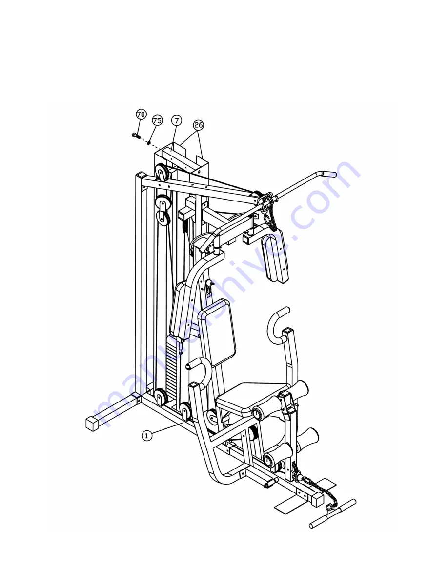
STEP 10   (See Diagram 10 & Cable Loop Diagram)


A.) Attach two Weight Plate Covers (#26) to the Weight stack. Secure it with four M10 x 1” Hex 

Bolts (#70) and four 

 13/16” Flat Washers (#75). 

B.) Securely tighten all nuts and bolts previously installed from Step1 through 10. 


DIAGRAM 

10


13 


Summary of Contents for APEX

Page 1: ...ntifier Assembly Instruction Parts List Resistance Chart Warranty Ordering Parts Model APEX Retain This Manual for Reference 06 24 02 OWNER S MANUAL MARCY HOME GYM APEX IMPEX FITNESS PRODUCTS 14777 DON JULIAN RD CITY OF INDUSTRY CA 91746 Tel 800 999 8899 Fax 626 961 9966 www impex fitness com info impex fitness com ...

Page 2: ...ng the machine As a manufacturer we are committed to provide you complete customer satisfaction If you have any questions or find there are missing or damaged parts we guarantee you complete satisfaction through direct assistance from our factory To avoid unnecessary delays please call our TOO FREE customer service number Our Customer Service Agents will provide immediate assistance to you Toll Fr...

Page 3: ...lothing when exercising DO NOT wear robes or other clothing that could become caught in the machine Running or aerobic shoes are also required when using the machine 7 Use the machine only for its intended use as described in this manual DO NOT use attachments not recommended by the manufacturer 8 Do not place any sharp object around the machine 9 Disabled person should not use the machine without...

Page 4: ...3 ...

Page 5: ...ear Base Frame 6 and the Rear Vertical Frame 5 to the back of the Base Frame 1 Align the holes and secure it with two M10 x 3 Hex Bolts 66 four 13 16 Flat Washers 75 and two Aircraft Nuts 78 C Attach the Front Vertical Frame 3 to the Base Frame 1 Secure it with two M10 x 3 Hex Bolts 66 four 13 16 Flat Washers 75 and two M10 Aircraft Nuts 78 D Attach the Upper Frame 2 to the top of the Front Vertic...

Page 6: ...Insert the Selecting Rod 22 into the center hole on the Plates Slide the Selector Stem 46 and the Top Weight Plate 83 onto the Guide Rods Align the hole and secure the Selector Stem 46 to the Selecting Rod 22 with a M10 x 1 9 16 Socket Bolt 82 C Attach the Top Socket Assembly 7 to the top of the Weight Plates Guide Rods 23 Secure it to the Upper Frame 2 with two M10 x 3 Hex Bolts 66 four 13 16 Fla...

Page 7: ...neath the Butterfly Support 13 See A View C Place a Butterfly Cable Guide 14 onto the axle on the Right Butterfly 12 Insert the Right Butterfly through the hole on the Butterfly Support 13 Secure it with a 1 Washer 32 M12 Aircraft Nut 77 and M12 Cone Shape Cap 52 D Attach a Butterfly Pad 41 to the Right Butterfly 12 and secure it with two M8 x 2 9 16 Allen Bolts 71 and two 11 16 Flat Washers 76 E ...

Page 8: ... E Insert a Foam Roll Tube 42 halfway through the hole on Leg Developer Holder 17 Push two Foam Rolls 43 onto the Tube from both ends Push two 3 Round Plugs 59 onto both ends of the Tube F Attach the Backrest Support Frame 19 to the Front Vertical Frame 3 Secure it with two M10 x 3 Hex Bolts 66 four 13 16 Flat Washers 75 one 2 x 4 Bracket 29 and two M10 Aircraft Nuts 78 G Attach the Short Quick Re...

Page 9: ...nd one M10 Aircraft Nut 78 on each side of the Front press D Lubricate the inside of the Foam Grips 44 with water and slide them onto the handlebars on the Front Press E Attach the Leg Developer 16 to the Leg Developer Holder 17 Secure it with one M12 x 3 3 8 Hex Bolt 64 two 1 x Bushings 80 two 15 16 Flat Washers 74 and one M12 Aircraft Nut 77 F Insert a Foam Roll Tube 42 halfway through the hole ...

Page 10: ... the bracket and secure it with one M10 x 1 Hex Bolt 69 two 13 16 Flat Washers 75 and one M10 Aircraft Nut 78 C Pull the Cable downward and attach a Pulley 60 and two Pulley Covers 61 in the mid span Attach a Single Floating Pulley Bracket 21 to the Pulley and secure it with one M10 x 1 Hex Bolt 69 two 13 16 Flat Washers 75 and one M10 Aircraft Nut 78 Let the Single Floating Pulley Bracket 21 hang...

Page 11: ...ley 60 and two Pulley Covers 61 to the Cable Attach the Double Floating Pulley Bracket 27 to the Pulley set and secure it with one M10 x 2 3 8 Hex Bolt 68 two 13 16 Flat Washers 75 and one M10 Aircraft Nut 78 D Draw the Cable upward towards the bracket underneath the Top Socket Assembly 7 Attach one Pulley 60 to the Cable and secure it to the bracket with one M10 x 2 3 8 Hex Bolt 68 two 13 16 Flat...

Page 12: ...y set on the second bracket E Pull the Cable upward towards the Double Floating Pulley Bracket 27 Install another Pulley set Draw the Cable over the Pulley set then downward F Attach another Pulley set and Single Pulley Bracket 21 Secure it with one M10 x 1 Hex Bolt 69 two 13 16 Flat Washers 75 and one M10 Aircraft Nut 78 Let the Bracket hanging for now G Pull the Cable upward and screw it at leas...

Page 13: ... Front Press 8 Attach another Pulley set to the Cable and secure it with one M10 x 5 11 16 Hex Bolt 65 two 13 16 Washers 75 two Plastic Spacers 45 and one M10 Aircraft Nut 78 NOTE See Detail B to install the Plastic Spacer D Draw the Cable backward through the hole at the bottom of the Front Vertical Frame 3 Attach another Pulley and secure it with one M10 x 2 9 16 Hex Bolt 67 two 13 16 Flat Washe...

Page 14: ...op Diagram A Attach two Weight Plate Covers 26 to the Weight stack Secure it with four M10 x 1 Hex Bolts 70 and four 13 16 Flat Washers 75 B Securely tighten all nuts and bolts previously installed from Step1 through 10 DIAGRAM 10 13 ...

Page 15: ...per 2 38 Leg Developer Bumper 1 39 Seat 1 40 Backrest 1 41 Butterfly Pad 2 42 Foam Roll Tube 2 43 Foam Roll 4 44 Foam Grip 2 45 Plastic Spacer 2 46 Selector Stem 1 47 82 Cable 1 48 150 Cable 1 49 113 Cable 1 50 121 Cable 1 14 51 M10 Cone Shape Cap 2 52 M12 Cone Shape Cap 2 53 2 Square Rubber Cap 4 54 2 Square Cap w hole 2 55 2 Square Curved End Cap 3 56 2 Square Flat End Cap 14 57 1 Square End Cap...

Page 16: ...t or other damages with respect to any economic loss loss of property loss of revenues or profits loss of enjoyments or use costs of removal installation or other consequential damages or whatsoever natures Some states do not allow the exclusion or limitation of incidental or consequential damages Accordingly the above limitation may not apply to you The warranty extended hereunder is in lieu of a...

Reviews: