background image

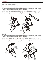
STEP 1

1. Remove two 

BOLTS (B4)

, two 

WASHERS (A21)

, two 

NUTS (A22)

 and a 


PACKING TUBE

 from the 

MAIN FRAME (A1).

2. Attach the 

FRONT STABILIZER (B1)

 to the 

MAIN FRAME (A1)

 using two 


BOLTS (B4)

, two 

WASHERS (A21) 

and two 

NUTS (A22) 

removed earlier.

STEP 2

1. Remove two 

BOLTS (B4)

, two 

WASHERS (A21)

, two 

NUTS (A22)

 and a 


PACKING TUBE

 from the 

MAIN FRAME (A1).

2. Attach the 

REAR STABILIZER (C1)

 to the 

MAIN FRAME (A1)

 using two 


BOLTS (B4)

, two 

WASHERS (A21)

 and two 

NUTS (A22) 

removed earlier.

7

ASSEMBLY INSTRUCTIONS :

Summary of Contents for IR 6500am

Page 1: ......

Page 2: ...RTANT INFORMATION PACKING LIST ASSEMBLY INSTRUCTIONS HOW TO MOVE THE TRAINER TELEMETRIC HEART RATE CHEST STRAP WARM UP COOL DOWN CLEANING MAINTENANCE RECYCLING INFORMATION ADDITIONAL INFORMATION 3 5 7...

Page 3: ...parts Keep others especially children at a safe distance while exercise g Make sure all devices are fully adjusted before use to avoid injury h Remove all jewelry including rings chains and pins befo...

Page 4: ...y physician The safety level of the equipment can be maintained only if it is examined regularly for damaged and wear The appliances are not for children under age of 14 IMPORTANT Read all instruction...

Page 5: ...E1 G1 5 PACKING LIST...

Page 6: ...Screw Driver 5mm 6mm 6 E6 screw M8 55mm 2PCS E7 washer M8 19 1 5T 2PCS G3 screw M8 20mm 2PCS screw M8 16mm 8PCS A12 screw M6 12mm 1PCS F33...

Page 7: ...to the MAIN FRAME A1 using two BOLTS B4 two WASHERS A21 and two NUTS A22 removed earlier STEP 2 1 Remove two BOLTS B4 two WASHERS A21 two NUTS A22 and a PACKING TUBE from the MAIN FRAME A1 2 Attach th...

Page 8: ...STEP 3 Attach the SEAT RAIL ADJUSTMENT BAR F34 to the SEAT FRAME F1 using SCREW F33 8 STEP 4 Attach the SEAT F35 to the SEAT FRAME F1 using four SCREWS A12 A12...

Page 9: ...the BACKREST FRAME F2 using four SCREWS A12 STEP 6 1 Connect the WIRE E8 of REAR HANDLEBAR E1 to the WIRE F42 of SEAT FRAME F1 2 Attach the REAR HANDLEBAR E1 to the SEAT FRAME F1 using two SCREWS E6 a...

Page 10: ...IN FRAME A1 using two SCREWS G3 3 Remove four SCREWS H2 from the back of the CONSOLE H1 4 Connect WIRES A15 A10 to the CONSOLE H1 and carefully tuck the wires into the MAIN FRAME A1 5 Attach the CONSO...

Page 11: ...1 Attach the RIGHT PEDAL D3R to the CRANK D4R using the wrench provided and rotate in the direction as the picture shown 2 Repeat the above step for the other side D4L D4R D3L D3R STET 9 11...

Page 12: ...h the floor 2 Move the trainer to your designated position while lifting the trainer 3 Carefully let down the trainer Make sure the trainer is placed on the flat floor and rotate the leveling foot clo...

Page 13: ...handle when the adjustment is complete 13 SEAT ADJUSTMENT SEAT LATERAL POSITION ADJUSTMENT To adjust the lateral position of the seat pull up the seat handle Then move the seat forward or backward to...

Page 14: ...14...

Page 15: ...ghtly slowly bend forward from the hips Allow your back and shoulders to relax as you stretch down toward your toes Go as far as you can and hold for 15 counts then relax Repeat three times Stretch Ha...

Page 16: ...l city office or the establishment where you purchased this product ADDITIONAL INFORMATION 1 The console requires 9V 1 3A adaptor 2 After 4 minutes of non use the console enters into power save mode a...

Reviews: