background image

Cheetah Python Cameras User Manual | CoaXPress (CXP) Interface


August 27, 2019 

Page 

17 

of

 86


Rev 1.0


 CXP Camera Connectors and 

Cables 

The coaxial cable(s)  connected to the camera provides power over CXP (PoCXP). The 

Camera’s video data output, control data, triggering, and general I/O’s are serialized and 

continuously transmitted over CoaXPress (CXP-6) using a  standard 75-ohm  mini-coaxial 

cable. Imperx offers two types of mini-coax cables: 1) a cable with a 1.0/2.3 DIN mini-coax 

push/pull plug on one end and a BNC connector on the opposing end; 2) a cable with a 

1.0/2.3 DIN mini-coax push/pull plug on both ends. The interface provides a high-speed 

downlink up to 6.25 Gbps for video transport and a lower speed 20  Mbps uplink for 

communication and control. 


The CXP output interface requires a CoaXPress frame grabber for collecting and storing the 

camera’s output. The frame grabber installs in the host computer and enables you to view 

images and configure the camera. 

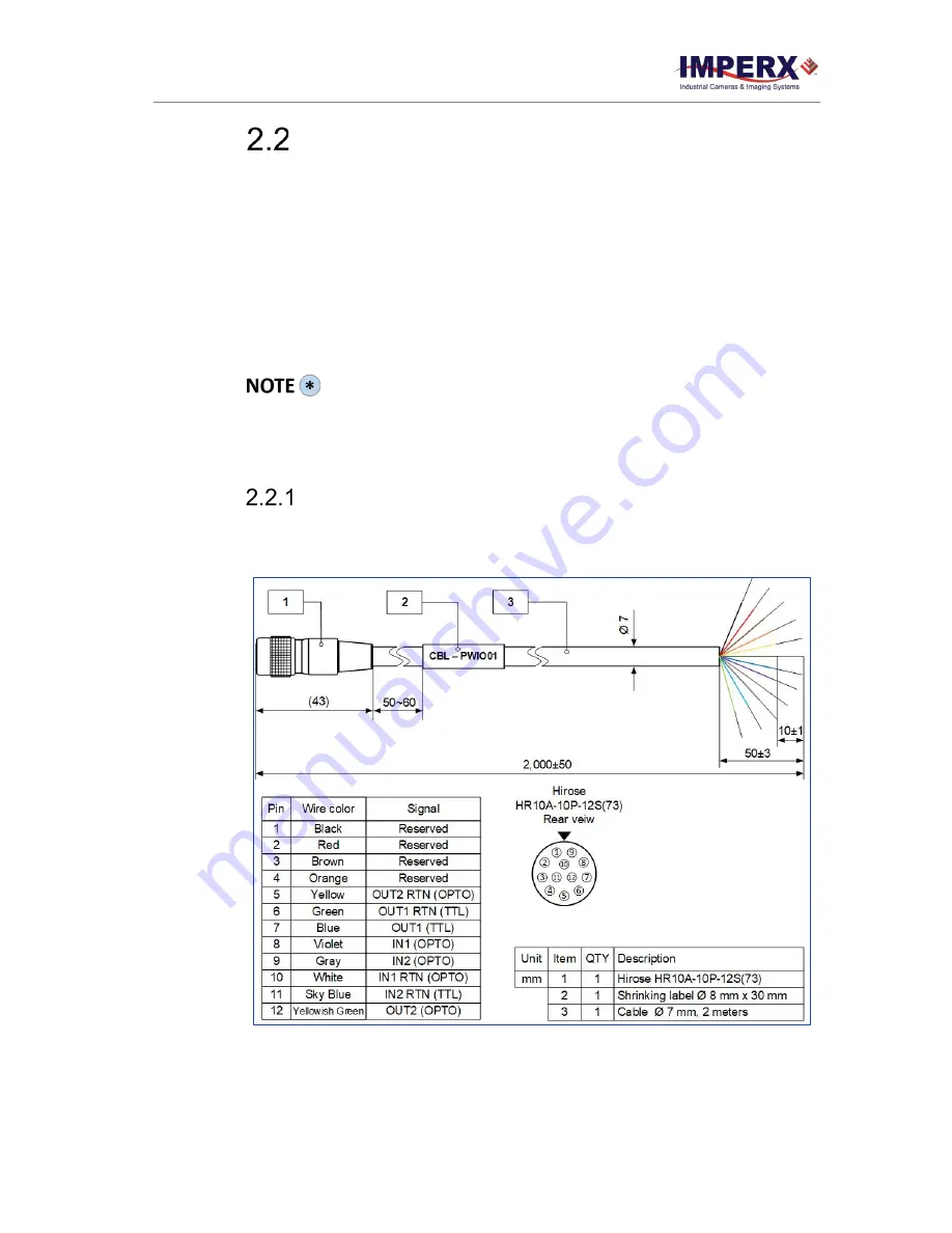
 I/O Cable 

The optionally purchased PWIO01 cable is used for transmitting external trigger and strobe 

signals. It terminates in a female HIROSE plug #HR10A-10P-12S(73) on one end and 12 loose 

wires on the opposing (see 

Figure 2

). 


Figure 2:

 CBL-PWIO01 cable (ordered separately) 


Summary of Contents for CXP-C4180C

Page 1: ...terface and GenICam compliant programming The ruggedized cameras use advanced 25 16 or 12 megapixel ON Semiconductor Python sensors industrial grade components and superior processing power to produce...

Page 2: ...applications including flat panel inspection biometrics aerial mapping surveillance traffic management semiconductors and electronics scientific medical Imaging printing homeland security space explor...

Page 3: ...ssumed by IMPERX for its use IMPERX reserves the right to make changes to this information without notice Redistribution of this manual in whole or in part by any means is prohibited without obtaining...

Page 4: ...or Pin Assignment 19 Electrical Connectivity 19 LED Status Indicators 22 Mechanical Optical Environmental 23 Mechanical Drawings 23 Mechanical Drawings of C5190 C4191 and C4190 24 Optical 25 Environme...

Page 5: ...lack Level Auto calibration and Offset 68 Data Output Format 68 Pixel Format 68 Pulse Generator 69 Input Output Control 69 Input Output Mapping 69 Test Image Patterns 70 Test Image Patterns 70 White B...

Page 6: ...Rev 1 0 Overview 78 Using an ASCII Text Editor 78 Using Microsoft Excel 79 Creating DPC HPC Tables 80 Overview 80 Editing DMP HPM Files 80 Finding defective pixels 81 Finding hot pixels 81 Locating an...

Page 7: ...Cheetah Python Cameras User Manual CoaXPress CXP Interface August 27 2019 Page 7 of 86 Rev 1 0 REVISION HISTORY Revision Date Reviser Comments 1 0 8 27 2019 R Johnston I Barabanova Initial Release...

Page 8: ...oaXPress cameras CXP C5180M 5120 x 5120 25 Mono 44 APS H NOIP1SN025KA CXP C5180C 5120 x 5120 25 Color 44 APS H NOIP1SE025KA CXP C5180N 5120 x 5120 25 ENIR 44 APS H NOIP1FN025KA CXP C4181M 4096 x 4096...

Page 9: ...ct for pixels that are over responding or under responding Auto White Balance AWB is available in color cameras to correct for color temperature The cameras have a 2 channel C5180 C4181 C4180 or 4 cha...

Page 10: ...pported Not Supported Supported Supported Supported Trigger Sources External Pulse generator Software Trigger over CoaXPress CXP External Pulse generator Software Computer External Pulse generator Sof...

Page 11: ...eraging mono 1x2 2x1 and 2x2 Auto white balance Yes Test image Static dynamic Defective pixel correction Static dynamic user DPM Hot pixel correction Static dynamic user HPM Inputs 1 LVTTL 1 Opto coup...

Page 12: ...C5180 35 6 fps 10 bit 44 fps 8 bit C5190 70 fps 10 bit 80 fps 8 bit Dynamic range 59 dB Shutter speed 50 s to 1 s Area of Interest One Analog gain 0 to 10 dB Digital gain 0 to 24 dB Black level offset...

Page 13: ...54 8 fps 10 bit 68 fps 8 bit C4191 107 fps 10 bit 120 fps 8 bit Dynamic range 59 dB Shutter speed 50 s to 1 s Area of Interest One Analog gain 0 dB to 10 dB Digital gain 0 dB to 24 dB Black level off...

Page 14: ...0 bit 90 fps 8 bit C4190 132 fps 10 bit 160 fps 8 bit Dynamic range 59 dB Shutter speed 50 s to 1 s Area of Interest One Analog gain 0 dB to 10 dB Digital gain 0 dB to 24 dB Black level offset 512 to...

Page 15: ...400 Color w out IR filter replace w clear cover glass 700 Mono w clear cover glass Note 000 none filter customization option means that a color camera has IR filter a monochrome camera does not have...

Page 16: ...0R 12PB 71 provides the general purpose I O interface 3 USB type B programming SPI connector 4 Status LED indicates the status of the camera 5 Serial Number shows camera model and serial number Figure...

Page 17: ...r on the opposing end 2 a cable with a 1 0 2 3 DIN mini coax push pull plug on both ends The interface provides a high speed downlink up to 6 25 Gbps for video transport and a lower speed 20 Mbps upli...

Page 18: ...the camera use CBL IO12 0002 cable to connect lens to the camera The CBL IO12 0002 cable is sold separately and used for transmitting power lens control trigger input and strobe output signals It term...

Page 19: ...OUT2 RTN General Purpose Output 2 Contact 1 Opto isolated 6 OUT1 RTN General Purpose Output 1 Return TTL 7 OUT1 General Purpose Output 1 TTL 8 IN1 General Purpose Input 1 Opto isolated 9 IN2 General P...

Page 20: ...imum input current must not exceed 2 0 mA Figure 6 IN2 electrical connection C Output OUT 1 TTL Output OUT1 is a 5 V TTL compatible signal and the maximum output current must not exceed 8 mA Figure 7...

Page 21: ...Page 21 of 86 Rev 1 0 Figure 8 Open drain logic driver Figure 9 Low side load driver Figure 10 High side load driver VS from 2 5 V to 25 V DC or peak AC R2 from 50R to 500R IL from 1 mA to 50 mA VS f...

Page 22: ...anel of the camera indicates camera status and mode of operation Table 9 Status LED LED Color Status Description Green steady ON Camera connected but no data being transferred Green Amber fast flash a...

Page 23: ...000 aluminum For maximum usability the camera has eight 8 M3X0 5mm mounting screws located towards the front and the back Cameras ship with an additional plate with 20 UNC tripod mount and hardware Al...

Page 24: ...Manual CoaXPress CXP Interface August 27 2019 Page 24 of 86 Rev 1 0 Mechanical Drawings of C5190 C4191 and C4190 Top view Side View with Image Plane Front View Back View Figure 12 Mechanical drawings...

Page 25: ...t source such as a laser beam This may damage the camera optical sensor 2 Avoid foreign particles on the surface of the imager Environmental The camera operating temperatures range from 40 C to 70 C i...

Page 26: ...s space You can program these registers and issue commands to retrieve data The Work Space is RAM based All camera registers clear upon camera power down The Factory Space segment is ROM based write p...

Page 27: ...by the User Set Default Selector The configuration spaces are Factory Space User Space 1 and User Space 2 3 The camera completes startup and accepts user commands GenApi Camera Configuration The foll...

Page 28: ...ming Convention SFNC used to create XML DeviceSFNCVersionMinor Integer RO Minor version of SFNC used to create XML DeviceSFNCVersionSubMinor Integer RO Subminor version of SFNC used to create XML Devi...

Page 29: ...nsorType Enumeration String Num Monochrome 0 Bayer 1 RO Returns the CMOS sensor type RgsID Integer RO Returns the RGS ID register FpgaID Integer RO Returns the FPGA ID 8 5AGXBA1D EpcsID Integer RO Thi...

Page 30: ...ger RO Returns CoaXPress magic number Revision Integer RO Returns revision of CoaXPress specification implemented in the camera XmlManifestSize Integer RO Returns number of XML manifests available in...

Page 31: ...h Integer RO Returns effective width of sensor in pixels SensorHeight Integer RO Returns effective height of sensor in pixels WidthMax Integer RO Returns max width of image in pixels calculated after...

Page 32: ...xelSize Enumeration String Num Bpp8 0 Bpp10 1 RO Indicates total size in bits of a pixel in an image PixelColorFilter Enumberation String Num None 0 BayerRG 1 BayerGB 2 BayerGR 3 BayerBG 4 RO Indicate...

Page 33: ...ge that goes from the darkest possible value to the brightest GreyVerticalRamp Image is filled vertically with an image that goes from the darkest possible value to the brightest GreyHorizontalRampMov...

Page 34: ...riety of read only information Figure 17 Sample Acquisition Control screen Table 14 Acquisition Control parameters Parameter Name Type Value Access Description AcquisitionMode Enumeration String Num C...

Page 35: ...an RW Enables AcquisitionFrameR ate and AcquisitionFrameP eriod features If enabled you can extend the actual frame time beyond the free running frame time AcquisitionFrameTime Integer Min MinFrameTim...

Page 36: ...rame time in 1 s increments RO Gets the exposure min and max time in microseconds TriggerMode Enumeration String Num Off 0 On 1 RW Enables the trigger mode of operation A trigger initiates an exposure...

Page 37: ...e or LevelHigh the exposure duration will be the time the trigger stays High If TriggerActivation is FallingEdge or LevelLow the exposure time will last as long as the trigger stays Low Timed Timed ex...

Page 38: ...B 1 87x 5 4 dB and 3 17x 10 dB gain BlackLevelAuto Enumeration String Num Off 0 Continuous 1 RW Controls the mode for automatic black level adjustment When set to Continuous this automatically adjusts...

Page 39: ...ed then gain is applied 3 4 6 1 AGC and AEC Controls Figure 19 Sample Auto Gain and Auto Exposure screen Table 16 Auto Gain and Auto Exposure parameters Parameter Name Type Value Access Description Ga...

Page 40: ...ureMaxExpr RW Sets max exposure time value for AEC in microseconds AgcAecLuminanceLevel Integer Min 1 Max 4095 RW Sets the desired luminance level to be maintained during AGC or AEC AgcAecLuminanceTyp...

Page 41: ...gital gain limit was reached during AGC operation AgcMaxLimitReached Integer RO Returns whether or not the maximum digital gain limit was reached during AGC operation AecExposureCurrentValue Integer R...

Page 42: ...when enabled LUTEnable Boolean RW Activates the selected LUT FFCSelector Enumeration String Num FFC1 0 FFC2 1 RW Selects which FFC is to use when FFC is enabled FFCEnable Boolean RW Activates the sele...

Page 43: ...increases as the value decreases You should set the hot pixel threshold using the longest expected exposure time with the longest expected frame time at the maximum expected ambient temperature The c...

Page 44: ...Sets white balance coefficient for green channel when WhiteBalanceAuto is set to Manual BlueCoefficient Integer Min 0 Max 4095 RW Sets adjusted white balance coefficient for blue channel when WhiteBal...

Page 45: ...n 1 RW Sets Strobe 1 mode of operation Strobe1Reference Enumeration String Num ExposureStart 0 ReadoutStart 1 RW Sets reference point for Strobe 1 Strobe1Width Integer Min 1 Max 1000000 RW Sets Strobe...

Page 46: ...String Num None 0 Trigger 1 PulseGenerator 2 Strobe1 3 Strobe2 4 RW Maps various internal signals to OUT1 output 3 4 9 2 OUT2 Table 23 OUT2 parameters Parameter Name Type Value Access Description OUT...

Page 47: ...3 RW Sets the multiplication factors of the Pulse Generator where x1 1 S x10 10 S and so on PulseGenWidth Integer Min PulseGenMin Max PulseGenWidthMax RW Sets pulse width of Pulse Generator in microse...

Page 48: ...etLensStatus runs 3 4 11 1 Controller Settings Figure 27 Sample Controller Settings screen Table 26 Controller Settings parameters Parameter Name Type Value Access Description InitLens Command WO Init...

Page 49: ...StepValue Integer Min 1 Max 255 RW Sets focus step to be moved with NearStep and FarStep commands FarStep Command WO Drives focus one step toward Far position by amount defined in FocusStepValue featu...

Page 50: ...Figure 29 Sample Iris screen Table 28 Iris parameters Parameter Name Type Value Access Description CurrentIrisPosition Enumeration String Num F0_7 0 F0_8 1 F0_9 2 F1_0 3 F1_1 4 F1_2 5 F1_4 6 F1_6 7 F...

Page 51: ...he fully opened position CloseIrisStep Command WO Closes iris by the amount defined in the IrisStepValue feature OpenIrisStep Command WO Opens iris by the amount defined in the IrisStepValue feature S...

Page 52: ...iguring communications between the camera with the CoaXPress interface Figure 30 Sample Transport Layer Control screen Table 29 Transport Layer parameters Parameter Name Type Value Access Description...

Page 53: ...register PixelFormatAddress Integer RO Returns the address of the PixelFormat information register DeviceTapGeometryAddre ss Integer RO Returns the address of the DeviceTapGeometry information regist...

Page 54: ...be read using CxpLinkConfigurationStatus CxpLinkConfigurationPref erred Enumeration String Num CXP1_X1 0x00010028 CXP2_X1 0x00010030 CXP3_X1 0x00010038 CXP5_X1 0x00010040 CXP6_X1 0x00010048 CXP1_X2 0...

Page 55: ...Code error count Writing a 0x0 clears the error counter RDErrorCount Integer RW Returns the low speed link s current 8B10B Running Disparity error count Writing a 0x0 clears the error counter CXPError...

Page 56: ...command MaxSpeedGradeCXPLink Integer RO Returns the Maximum speed grade of the CXP link NumberOfChannelsCXPL ink Integer Min 0 Max MaxNumberOfChannels CXPLinkReg RW Sets the number of channels of the...

Page 57: ...rSet0 1 UserSet1 2 RW Enables selection of User Set to load save or configure UserSetLoad Command WO Loads User Set specified by UserSetSelector to camera and makes it active UserSetSave Command WO Sa...

Page 58: ...a and on GenICam transport layer streaming Figure 34 Sample Special Features screen Table 33 Special Features parameters Parameter Name Type Value Access Description DeviceStreaming Integer RO Returns...

Page 59: ...he array begins In this way all pixels capture the image during the same period which reduces any image artifacts due to motion within the scene The maximum exposure is frame time dependent and the mi...

Page 60: ...2 Programmable Frame Time Control After adjusting the Pixel Clock Rate to minimize the line read out time you can increase the frame time using the programmable Frame Time function When enabled the se...

Page 61: ...Bit Depth Frame Rates at Full Resolution C5180 8 44 0 fps C5190 8 80 0 fps 10 35 6 fps 10 70 0 fps C4181 8 68 0 fps C4191 8 120 0 fps 10 54 89 fps 10 107 0 fps C4180 8 90 0 fps C4190 8 160 0 fps 10 7...

Page 62: ...ontal Window and the vertical direction Vertical Window by setting the window H V offset and H V size as shown in the following figure The minimum window size is 320 H x 2 V pixel line and the horizon...

Page 63: ...andwidth of the output interface can impact the maximum achievable frame rate 4 3 3 1 AOI Frame Rate Examples The following table provides examples of frame rate from various AOI s using the CXP outpu...

Page 64: ...image or within any area of interest For example if the area of interest is defined as quad full HD 3840 x 2160 and 4 1 averaging is selected the output is 1080P 1920 x 1080 Subsampling Decimation Su...

Page 65: ...ing mode the camera receives the trigger signal from the internal pulse generator Software the camera expects a computer to send a command to the camera for generating one short trigger pulse You can...

Page 66: ...era idles and waits for a trigger signal Upon receiving the trigger signal the camera starts integration for the frame then completes the integration and reads out the image If the next trigger occurs...

Page 67: ...ideo Amplifier Gain and Offset Analog Gain The cameras provide 1x 0 dB 1 26x 2 0 dB 1 87x 5 43 dB and 3 17 10 0 dB analog gain Always apply analog gain before applying digital gain Digital Gain Digita...

Page 68: ...he black level auto calibration engaged If auto calibration is disabled you can set the Black Level Offset and adjust it by 511 counts Black level will vary with temperature and gain settings Data Out...

Page 69: ...he amount of time also determined by the granularity between consecutive pulses Minimum value is 1 maximum is 1 048 575 Period Width Figure 44 Internal pulse generator Input Output Control Input Outpu...

Page 70: ...gorithm to compensate for this effect With white balance correction enabled the camera collects the data for all of the image sensor s red R green G and blue B pixels analyzes the data and adjusts the...

Page 71: ...tandard Gamma Correction The image generated by the camera is normally viewed on a monitor and does not have a linear transfer function that is the display brightness is not linearly proportional to t...

Page 72: ...the factory final testing identifies and corrects up to 1024 defective pixels using defective pixel correction Two types of defective pixels are possible Dark a pixel whose sensitivity is lower than t...

Page 73: ...4181 and C4180 cameras use a factory installed flat field correction located in FFC1 algorithm to correct some of the image sensor s non uniformity and employs an algorithm to correct the fixed patter...

Page 74: ...r the current image size by issuing a command The camera will return current camera image size in pixels x lines refer to the Table 13 Image Format parameters Auto Gain and Auto Exposure Control AGC A...

Page 75: ...out of the next frame begins Unlike traditional CCD image sensors the CMOS image sensor digitizes each pixel within a row simultaneously This allows for more settling time which lowers the overall noi...

Page 76: ...Cheetah Python Cameras User Manual CoaXPress CXP Interface August 27 2019 Page 76 of 86 Rev 1 0 Figure 48 Typical CMOS image sensor architecture...

Page 77: ...s Figure 49 Python CMOS mono spectral response monochrome cover glass Figure 50 Python CMOS typical color spectral response micro lens cover glass Bayer Pattern Information Cheetah Python cameras are...

Page 78: ...file must be renamed to include the lut file extension The lut file has two main sections a header and a table The header section is a free text area of up to 256 ASCII characters Each line of the hea...

Page 79: ...be created in Excel as follows 1 Create the spreadsheet as shown below note that 4096 rows are required in the table 2 Add the necessary equations into the output cells to generate the transfer funct...

Page 80: ...pad or any other editing software The files look like this Defective Pixel Map Date 2 23 2018 Model CLF C5180M CF Serial LAC001 Table Column X Row Y 5683 155 3091 332 3532 893 650 1017 701 1017 1712 1...

Page 81: ...eps below to find first pixel coordinates locate and adjust defective pixel coordinates and accurately place defective pixel coordinates into the pixel map STEP 1 Find the First Pixel Coordinates Your...

Page 82: ...593 is row and Y 4816 is column you would have had to transpose the coordinates to 4816 593 Figure 52 Frame grabber s firs pixel Figure 53 Locating defective pixel a Click the first pixel b This frame...

Page 83: ...4325 1019 2241 1020 458 1021 1712 1053 914 1067 3954 1546 2516 1670 3451 3331 1111 4149 95 4364 594 4817 433 4828 205 4899 Defective Pixel Map Date 4 12 2018 Model CXP C5180M RF Serial LAC001 Table C...

Page 84: ...ll pixels are listed in the DPM or HPM in order of increasing Y row location If the Y location is identical the listing is in order of increasing X column location The maximum number of pixels in the...

Page 85: ...uploads of DPM HPM and other files to your camera To upload DPM and HPM files 1 Connect and power up your camera 2 Start the Imperx Upload Utility and wait for the Utility to detect the camera Figure...

Page 86: ...ure 56 Supported upload files 5 After the upload is completed do a power cycle on the camera 6 After the camera re starts start your software GUI and select Data Correction 7 Ensure that DPC and HPC a...

Reviews: