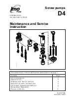
background image

Screw pumps

Maintenance and Service
Instruction

D4 0617GB

December 2000

This instruction is valid for all D4 pump models shown on page 2

Contents

Page

List of components

2

Exploded view

3

Ordering code/Service intervals

4

Inspection of rotors/Sectional view

5

List of tools/Inspection of shaft seal

6

Dismantling/Reassembly

7

Pressure relief valve

11

D4 1 © IMO 

AB

A Member of the
COLFAX PUMP GROUP

D4

Summary of Contents for D4

Page 1: ...or all D4 pump models shown on page 2 Contents Page List of components 2 Exploded view 3 Ordering code Service intervals 4 Inspection of rotors Sectional view 5 List of tools Inspection of shaft seal 6 Dismantling Reassembly 7 Pressure relief valve 11 D4 1 IMO AB A Member of the COLFAX PUMP GROUP D4 ...

Page 2: ...ower rotor CCW rot 1 x x 102 Power rotor CW rot 1 x x 113 Key 1 x x x 1030 Valve 1 x x x 124 Retaining ring 1 x 13 124A Support ring 1 x 13 124B Washer 1 x 13 139 Balancing washer 1 139A Retaining ring 1 x 13 201 Idler rotor CCW rot 2 x x 202 Idler rotor CW rot 2 x x 376 Balancing bush 2 x x x 382 Screw 4 7 391 Plate 1 7 395 Support plate 1 x 395A Screw 2 x 401 Pump body 1 x 423 O ring 1 10 427 Sp...

Page 3: ...BP size 025 032 4 Only for xxBP size 038 052 5 Not for xxBP 6 Valid for xxBP size 025 032 060 070 7 Valid for xxTE 8 Valid for xxTE xxJE 9 Not for xxTE 10 Valid for xxJE 11 Valid for xxBP 12 Valid for xxBP sizes 025 052 13 Valid for sizes 025 xxJE xxBE xxTE xxBP 025 032 038 052 060 070 520 520A 507 509 521 521A 506 463 463A 401 113 102 202 376 501 1030 451 451A 395 395A 556 551 427 428A 428 491 48...

Page 4: ...vated pressure fluid jets may cause injury and or damage Oil leakage may make the floor slippery and cause personal injury Before any maintenance work ensure that the driver is deenergized and the pump hydraulically isolated Connecting and disconnecting of electric cables must be done only by personnel authorized to do such work Recommendation for maintenance Every shut down for service of a plant...

Page 5: ... 11 Internal clearances in the pump which are vital for its proper function may have been affected by wear Acceptable wear can be determined only by experi ence of the actual application As a rule of thumb the following max clearance values may apply Between rotor and bores or bushings 0 2 mm Between rotor flanks 0 2 mm For light duties low pressure medium viscosity even bigger clearances may be a...

Page 6: ...seals should be changed without delay as the leakage normally will grow worse and cause additional damage Follow the instructions in the dismantling reassembly session When working with a shaft seal cleanliness is of utmost importance Avoid touching the seal faces If necessary the seal faces should be cleaned immedi ately prior to assembly using a dust free cloth and clean solvent Never use grease...

Page 7: ...ng S2 from the seal cover 520 D4 10 IMO AB A B Dismantling Fig 5 Fig 6 Note the axial position of the shaft coupling Release the stop screw Remove the shaft coupling with a puller D4 7 IMO AB Turn the electricity OFF Close the valves Remove the pump from the system ATTENTION Use appropriate vessels to collect oil spill age when removing and opening the pump 521A 113 520 ATTENTION Protect the face ...

Page 8: ...the shaft seal bellows unit S5 and the seal ring S4 E F ATTENTION Protect the face of S4 S4 451A 451 401 501 Fig 10 Fig 9 D4 13 IMO AB 202 D4 14 IMO AB Separate the front cover 501 and the power rotor 102 Inspect the rotors balancing bushes 376 and O ring 506 by separating them G H ATTENTION Be careful not to make scratches in the surfaces of the balancing piston bore 506 501 102 Fig 12 Fig 11 376...

Page 9: ...ont cover 501 See fig 12 Lubricate the rotor set Assemble it including balancing bushes 376 D4 20 IMO AB Carefully insert the rotor set into the pump body 401 Watch the position of O ring 506 Make sure the bolt holes match Fit the screws 451 and the washers 451A Tight the screws crosswise D4 18 IM O AB D Fig 16 Fig 17 E 376 501 102 451A 451 401 501 506 Fig 13 B Check prior to assembly by mounting ...

Page 10: ...fig 6 Put the pump back into the system and proceed according to instructions under Start up in the installation manual S4 D4 22 IMO AB Fit the O ring S2 in the seal seat S1 Fit the seat S1 in the seal cover 520 Lubricate the power rotor shaft the bellows unit S5 and the seal ring S4 Fit the bellows unit S5 into the front cover 501 Fit the seal ring S4 Note the position of the drive notches on S4 ...

Page 11: ...025 052 Loosen cover 601 and remove it together with the nut by using the valve spindle Remove retainer 608A or C Pull out the valve spindle 608 or 608B and replace the O ring 605 060 070 Remove cover 601 by removing screws 455 and remove spring washer 611 Remove screw 609A and washer 609 Unwind the spindle 608 Replace the O ring 605 Remove spring 615 and valve piston 614 Replace valve piston if i...

Reviews: