8
www.imo.se
AC
F/
U
C
F5 2
01
9.
12 e
n-
G
B
, I
D
-N
o.
: 1
63
-0
44
/B
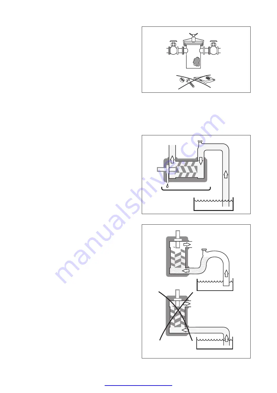
Fig. 11 Liquid trap
Fig. 9 Strainer
Strainer
The pump has to be protected from foreign matter,
such as weld slag, pipe scale, etc., that could enter
the pump via the suction line. If the cleanliness of
the system cannot be guaranteed, a strainer must
be installed in the inlet pipe near the pump. For
practical reasons a suction strainer with 0.6 mm
mesh openings is recommended:
The size of the strainer should be selected so that
it is large enough to allow adequate pressure at the
pump inlet. The pressure drop across the strainer
should preferably not exceed 0.1 bar at max. flow
rate and normal operating viscosity. A vacuum
gauge between the strainer and the pump inlet is
recommended to indicate when the strainer needs
cleaning.
Note: The service life of the pump is decisively
influenced by the degree of contamination of the
fluid being conveyed, that means, by the number,
size and hardness of the abrasive components.
Shaft seal drain
The pump should be installed so that any leakage
from the shaft seal does not become a hazard. As
the shaft seal has to be lubricated a small amount of
oil dripping cannot be avoided.
Provisions to collect the leakage from the shaft seal
must be made.
A drain pipe can be connected to the drain
connection on the pump, (not applicable to pump
series LPD). However, when pumping heavy fuel
oil or any other liquid that is likely to become very
viscous at ambient temperature, we recommend
that the liquid is allowed to drop freely from the drain
opening.
Liquid trap
In some mounting arrangements the pump may not
retain the liquid at stand still. In such installations the
suction pipe should be arranged so it forms a liquid
trap together with the pump, keeping the pump half
filled with liquid. See fig. 11.
Fig. 10 Shaft seal drain
www.northridgepumps.com


