Immergas 3.03160 Instruction And Warning Book Download Page 18

18

System choice.

SySt

” parameter (Default value “

1

” cannot be modified).
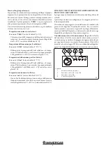
System 1.

Base system, with 1 tank, 1 pump, series of manifolds and 2 

sensors. It can be enriched with extra functions with 1 or 2 

sensors T3 (NTC) or T4 (PT1000) (Thermostat, Cooling, An-

ti-stagnation or diff Control function).

P1

T1

T2

11

Tank 1 charging is possible if the temperature difference “

dt

between the collector (T1) and tank 1 (T2) is sufficient.

Choice of the manifold.

TubE

” parameter (Default value “off”).

Once the “

TubE

” parameter has been selected, press the naviga-

tion key to the right (▶+) to choose the type of manifold installed.

-  At this point select “on” if your system uses a vacuum pipe 

manifold. (This function can also be used with a flat manifold if 

the sensor is mounted on the outer parts of the manifold). This 

function works as follows. Every 30 minutes the pump runs 

for 40 seconds to measure the correct value on the manifold 

and avoid a cycle with short charge.

-  Select "off" if the system works with a flat manifold under 

normal conditions of use. 

Manifold maximum temperature.

ColM

” parameter (Default value “120”).

-  Set the level to start the overheating protection for the man-

ifold (Adjustable from 110 to 150°C, with factory setting at 

120°C).

Overheating protection.

OvrH

” parameter (Default value “On”).

This function will stop the circulations of all manifolds (P1 and 

P2) when the manifold temperature increases above “

ColM

” 

plus a compensation value (default value +10°C, modifiable). 

This function is used to protect the system elements (pipes, 

fittings, ring seals ..).

-  To activate the function press (▶+) selecting "on”.
-  The compensation level can now be adjusted. 

Ovrt

” parameter (Default value “20°C”).

This compensation is generally used to avoid a too fast reaction 

of the overheating protection function (especially useful with 

the vacuum pipe manifold).

(Adjustable from +10°C to +30°C with factory value +10°C).

N.B .: for safety reasons, the overheating protection must 

always be “on”.
Cooling.

Cool

” parameter (Default value “On”).

This option is used to protect the manifold liquid and works 

as described below. It activates the solar pump 

P1

 or 

P2

 if the 

temperature on the series of manifolds 

T1

 or 

T4

 exceeds the 

Max temp

” value even if the maximum temperature set in the 

tank is exceeded. Circulation stops when the temperature has 

dropped by 10°C (The pumps stop if the water temperature in 

the tank reaches 90°C).

Rcoo

” parameter (Default value “On”).

When the water temperature in the tank exceeds the "Maxtemp 

tank1" setting level and the manifold temperature has dropped by 

10°C, the pump is activated to cool the tank through manifolds. 

The pump will turn off when the water temperature drops to the 

"

tkM1

" setting level or when the difference between the tem-

perature of the series of manifolds and the tank is less than 2°C.

Anti-freeze protection.

FrEZ

” parameter (Default value “off”).

This option keeps the temperature of the solar panel 

T1

 or 

T4


above the level set for frost with the “

Frzt

” parameter by acti-

vating pump 

P1

 or 

P2

.

This option can be used to reduce the accumulation of snow on 

the panel and increase efficiency during the day or avoid damage 

to the solar liquid.

N.B .: it is preferable not to use this function in areas that are 

too cold to avoid using too much energy stored in the tank.

-  To activate the function, press (▶+) and select "on”.
-  The Freeze setting level can now be adjusted.

FrZt

” parameter (default value “10°C” (Adjustable from -20°C 

to + 7°C with recommended value 3°C).

Display.

DiSP

” parameter (Default value “OFF”).

Backlight function.

-  To disable or disable the backlight function, press (▶+) or (-◀).
-  If it is “

Off

” the backlight will turn off automatically 3 minutes 

after pressing the button. 

-  If it is “

On

” the backlight will always be active.

Factory setting.

Fact

” parameter.

-  If you want to reload all the parameters with the factory values, 

hold down the (▶+) key for a few seconds.

N.B.: for reasons of protection from errors and security rea-

sons, the chosen system will not be reset.
Setting menu (setting)

In this menu you have all the adjustable parameters for your 

system. The various parameters are not available on all systems.
To access the Setting menu, press the (-◀) and (▶+) keys simul-

taneously. Once you have entered the Installation menu (the first 

parameter “

TkM1

” is displayed), it is possible to choose another 

parameter by pressing the navigation key (

OK

). 

Once the desired parameter is displayed, it is possible to change 

Summary of Contents for 3.03160

Page 1: ...OD 3 031603 KIT ABBINAMENTO IMPIANTO SOLARE TERMICO PER TRIO PACK ELECTRIC THERMAL SOLAR SYSTEM COMBINATION KIT FOR TRIO PACK ELECTRIC IT Foglio istruzioni e avvertenze Instruction and warning book IE...

Page 2: ...ruzioni acorredo del prodotto per una corretta installazione dello stesso L installazione e la manutenzione devono essere effettuate in ottemperanza alle normative vigenti secondo le istruzioni del co...

Page 3: ...ordo 2 ed al tubo 3 interponendo le relative guarnizioni N B assicurarsi che il lato con la scritta HOT della valvola miscelatrice sia rivolto verso l alto come evidenziato in Fig 2 Fissareilgrupposol...

Page 4: ...dicato in Fig 4 e bloccarla in posizione avvitando le viti 8 fornite in dotazione Montare il vaso 9 sulla squadretta 7 Completare il mon taggio fissando la valvola di sicurezza 10 il tubo 11 ed il rac...

Page 5: ...ra 15 utilizzando le viti 14 fornite in dotazione Montare la lamiera 15 sul gruppo solare 16 come indicato in Fig 5 e fissarla utilizzando la vite 17 fornita in dotazione Fissare lo scambiatore a pias...

Page 6: ...i nel kit tubo RP MP lungo UCS RP corto EFS Collegare i due tubi del sistema solare ai raccordi apposita mente predisposti utilizzando una delle asole pretranciate predisposte B Collegare il tubo in s...

Page 7: ...zare il sensore desiderato Men installazione Premere per 5 secondi il tasto OK per accedere al menu di installazione Quando si accede al menu di installazione viene visualizzato il primo parametro Sys...

Page 8: ...on valore di fabbrica 10 C N B per motivi di sicurezza la protezione dal surriscalda mento deve essere sempre su on Raffreddamento Parametro Cool valore di default On Questa opzione viene usata per pr...

Page 9: ...pompa principale 1 Regolabile da 2 a dTMax serb 1 2 C con valore consi gliato 3 C Temperatura minima sul collettore Parametro mtCo valore di default 25 C Questo livello di impostazione viene usato pe...

Page 10: ...Y Y On Off Off On Off Situazione anomala il circola tore continua a funzionare bassa tensione di alimenta zione Tensione fuori range 160 Vac Controllare l alimentazione elettrica R Y Y Y Y On Off On O...

Page 11: ...tegrazione impianto Optional K70 A B Rel multifunzione Optional M1 HP Circolatore pompa di calore S20 1 Termostato ambiente zona 1 Optional S20 2 Termostato ambiente zona 2 Optional S36 1 Umidostato z...

Page 12: ...d with the product carefully to ensure proper installation Installation and maintenance must be performed in compliance with the regulations in force according to the manufacturer s instructions and b...

Page 13: ...to the fitting 2 and to the pipe 3 interposing the relative gaskets N B make sure that the side with the word HOT of the mixing valve faces upwards as shown in Fig 2 Secure the solar unit 4 to the met...

Page 14: ...t plate 5 supplied as indicated in Fig 4 and lock it in place by tightening the screws 8 supplied Mountthevessel 9 onthebracket 7 Completethe assembly by fixing the safety valve 10 the pipe 11 and the...

Page 15: ...13 on the metal sheet plate 15 using the screws 14 supplied Mount the metal sheet plate 15 on the solar unit 16 as shown in Fig 5 and secure it using the screw 17 supplied Secure the plate exchanger 1...

Page 16: ...interpose the flat gaskets present in the kit RP MP long UCS RP short EFS pipe Connect the two solar system pipes to the specially prepared fittings using one of the pre cut slots B Connect the silico...

Page 17: ...o display the desired sensor Installation menu Press the OK key for 5 seconds to access the installation menu When accessing the installation menu the first parameter Syst is displayed it is possible...

Page 18: ...P2 if the temperature on the series of manifolds T1 or T4 exceeds the Max temp value even if the maximum temperature set in the tank is exceeded Circulation stops when the temperature has dropped by...

Page 19: ...to define a minimum temperature on the manifold to authorize solar charging Adjustable between 0 C and 99 C with default value 25 C CIRCULATION PUMP THERMAL SOLAR SYSTEM COMBINATION KIT The units are...

Page 20: ...ic the pump is set in Constant curve speed 3 by default Real time diagnostics in the event of a malfunction the LEDs provide information on the operating status of the pump see table Fig 14 Pump Led F...

Page 21: ...System integration resistance relay Op tional K70 A B Multifunction relay Optional M1 HP Heat pump circulator S20 1 Room thermostat zone 1 Optional S20 2 Room thermostat zone 2 Optional S36 1 Zone 1 h...

Page 22: ...22...

Page 23: ...23...

Page 24: ...ducts that are correctly installed and used with respect to the Standards in force N B correct periodic maintenance is highly recommended Immergas TOOLBOX L App studiata da Immergas per i professionis...

Reviews: