


24
12
29a
29b
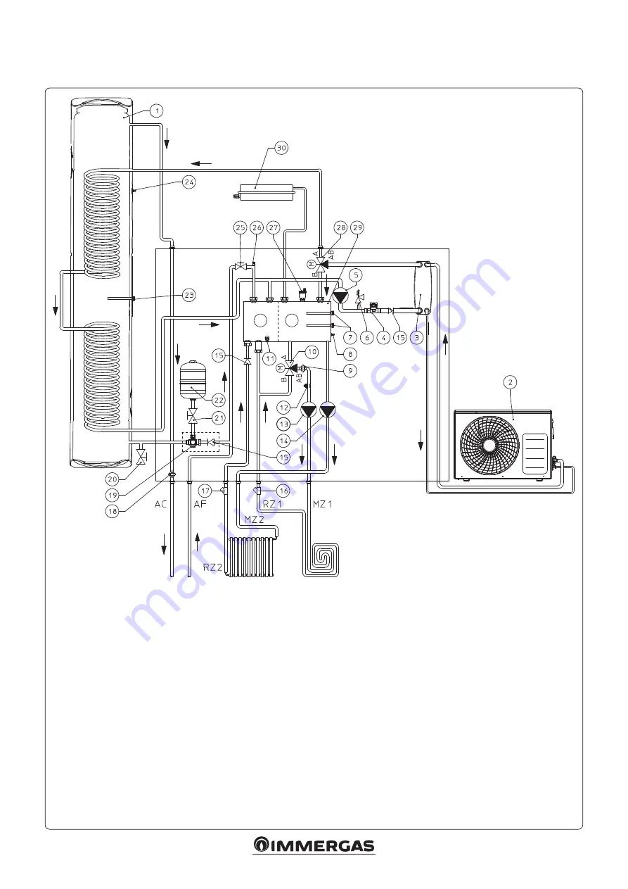
HYDRAULIC DIAGRAM FOR THE CONNECTION OF THE TRIO PACK ELECTRIC WITH MIXED SECOND ZONE
KIT IN SOLAR OR DOMUS CONTAINER.
Key:
1
- Tank unit
2
- Outdoor Condensing Unit
3
- Plate heat exchanger
4
- System flow meter
5
- System circulator
6
- 3 bar safety valve
7
- System resistance (optional)
8
- System flow probe
9
- Safety thermostat
10 - 3-way Mixing valve (optional)
11 - Manifold draining valves
12 - Mixed zone flow probe (optional)
13 - Mixed zone pump / circulator (optional)
14 - Direct zone circulator
15 - One-way valve
16 - Inspectionable filter (optional)
17 - Inspectionable filter
18 - Antifreeze thermostat
19 - 8 bar safety valve
20 - Tank unit draining valve
21 - DHW vessel shut-off valve
22 - DHW 8 l expansion vessel
23 - DHW electric heating element
24 - Boiler probe
25 - Filling valve
26 - Manual vent valve
27 - Automatic vent valve
28 - 3-way valve (Motorized)
29 - Hydraulic manifold
29a - Manifold delivery sector
29b - Manifold return sector
30 - System 8 l expansion vessel
AC - Domestic hot water outlet
AF - Domestic cold water inlet
MZ1 - Mixed zone system delivery
RZ1 - Mixed zone system return
MZ2 - Direct zone system delivery
RZ2 - Direct zone system return


