


de
fr
en
nl
Safety, Installation and Storage Instructions
These instructions are intended for trained
personnel. They must be read before starting
commencing installation work and stored in a
safe place by the operator.
Personnel must possess the
appropriate skills and training.
Store horizontally in dry rooms, in the original packaging.
Prior to assembly, a visual inspection of the Ferro-Cleaner
filters has to be performed. If there is any major damage,
the Ferro-Cleaner filters should not be used.
Measures conforming to regulations must be taken to
ensure that admissible temperatures and pressures are
not exceeded.
Applicable local fire regulations must be adhered to.
Access to the place of installation must be restricted to
trained and specialised personnel.
Before carrying out any assembly, disassembly or main
-
tenance work on a Ferro-Cleaner filter, the system must
be depressurised and allowed to cool. Ball valves/shut-off
flaps must be closed. When carrying out assembly and
maintenance work, pay attention to the following symbols
and information:
Important: High temperatures
and pressurised hot water!
Magnetic effect: Protect data
media and heart pacemakers!
Application
|
Technical data
•
Magnetic flux filter for separating magnetite
•
Heating, solar and chilled water systems
•
Up to 50 % antifreeze
•
Max. adm. temperature TS: -20
–
120 °C
•
Max. adm. pressure PS: 16 bar
•
Function does not depend on flow direction.
•
Max. flow velocity in continuous operation: 1 m/s
•
Alternatively Ferro-Cleaner can be used with a magnesium
anode for reduction of oxygen within a system.
Applications other than those described require prior
agreement with IMI Hydronic Engineering.
Materials
•
Body:
Brass
•
Gaskets: Beater seals -20
–
120 °C
•
Anode (optional): Magnesium
Installation
Ferro-Cleaner filters can be installed horizontally or verti
-
cally. For horizontal installation, we recommend positioning
the magnets at the top (easier to clean, minimum water loss
during cleaning). For vertical installation, the fitting can be
vented on the flange or the housing.
Type 80 filters are connected using a 1
¼"
thread. Type 150
filters are connected using a DN flange connection. If pos
-
sible, the ball valves/shut-off flaps should be assembled
directly next to the Ferro-Cleaner.
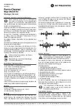
Type 80
Type 150
Operation
|
Maintenance
Ferro-Cleaner filters must be emptied and cleaned
at regular intervals as appropriate for the amount
of magnetite and dirt in the system water.
*
As the magnet is located directly in the flow, water loss can
occur during disassembly. Positioning the magnet at the top
makes cleaning easier.
Maintenance procedure:
1. Switch off the circulating pump
2. Close the ball valves/shut-off flaps
3. Turn the drain cock to depressurise the Ferro-Cleaner
4. Pull out the magnetic rod/anode
5. Control and clean the magnet/anode *
6. Re-insert the magnetic rod /anode
7.
Open the ball valves/shut-off flaps
8. Check for leaks
Please note that there is materal consumption of the mag-
nesium anode. The anode has to be replace after a certain
period of time depending on the system.
*
The quantity of water removed by draining must
be replaced, otherwise the pressure maintenance
function will be impaired.
Regulations
|
Inspection
Ferro-Cleaner filters fall within the scope of Article 3
Paragraph 3 of the Pressure Equipment Directive
PED/2014/68/EU. There are therefore no inspection pro
-
cedure standards. Local regulations and environmental
requirements must be adhered to.
IMI Hydronic Engineering Switzerland AG •
Mühlerainstrasse 26
•
CH-4414 Füllinsdorf
•
Tel. +41 (0)61 906 26 26
•
www.imi-hydronic.com
Ferro-Cleaner
Magnetic Flux Filters
Installation | Operation
WZMOIN0007
02.2019


