


20
EnglishEnglish
“Wrong!” will appear: Confirm the message and re-enter the pass-
word .
7.4.1 View “Work Mode”
In this view, the operating mode can be selected (cf . chapters 6 .2 .2
and 6 .3 .2):
Fig. 12 Operating mode
On the left, select the operating mode desired: STEREO, PARALLEL or
BRIDGE . In the modes PARALLEL and BRIDGE, the lock on the right
will be closed to indicate that all parameters are linked . Only the op-
erating mode STEREO will allow independent settings for channel B .
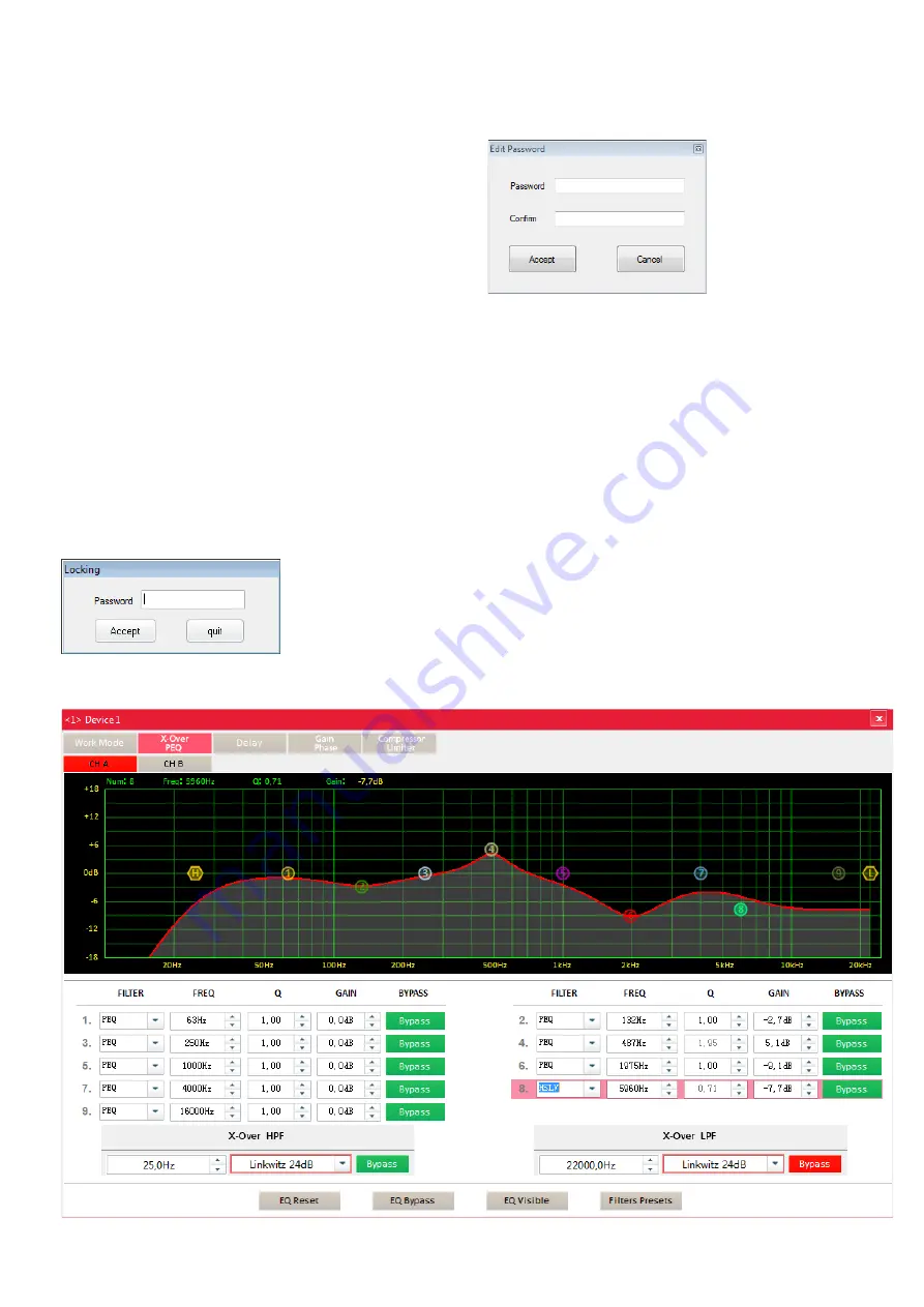
7.4.2 View “X-Over, PEQ”
The view “X-Over, PEQ” (fig . 13) provides a summary of all filter
settings . This includes the 9 filters of the parametric equalizer that
can be used to compensate acoustic problems of a room or speaker,
for example, and the high-pass filter and low-pass filter that can be
used as a crossover network, for example (
☞
chapter 8) . The curve
in the diagram shows the magnitude frequency response (= result of
all filters of a channel) . To select the channel to be shown, use the
buttons CH A and CH B above the diagram .
In the diagram, each filter is represented by a marking . To hide/
show the markings of the 9 filters of the parametric equalizer, use
the button “EQ Visible” .
7.4.2.1 Numerical filter setting
Use the input fields beneath the diagram to make the filter settings .
For the 9 filters of the parametric equalizer, the following values can
be set (cf . chapter 6 .3 .4):
Filter characteristic FILTER:
PEQ
Bell characteristic
LSLV
Low Shelving characteristic
HSLV
High Shelving characterstic
Filter frequency FREQ
Quality factor Q
Gain or attenuation GAIN
Use the button BYPASS to activate or deactivate the filter:
Red:
deactivation of the filter
Green:
activation of the filter
All 9 filters can be activated or deactivated by means of the button
EQ BYPASS .
In the lower section, the settings for the high-pass filter HPF and low-
pass filter LPF can be made (cf . chapter 6 .3 .3):
In the left field, select the crossover frequency; in the right field, select
the filter type:
– Butterworth filter; slope: 6, 12, 18 or 24 dB /octave
– Bessel filter; slope: 12 or 24 dB /octave
– Linkwitz-Riley filter; slope: 12 or 24 dB /octave
Use the button BYPASS to activate or deactivate the filter .
Fig. 13 View “X-Over, PEQ”
7.3.4 Data backup via the computer
It is possible to save all settings of the amplifier on the computer, either
for data backup or for transfer to another amplifier . For this purpose,
the following menu items are available:
Memory
Export Parameters:
to save the current settings to the computer
Memory
Import Parameters:
to load the saved settings from the computer
Memory
Make Factory:
to save all presets of the amplifier to the computer
Memory
Load Factory:
to load all presets of an amplifier from the computer to the
amplifier
7.3.5 Changing the password
As described in chapter 6 .1, a password will protect the amplifier
against unauthorized operation . The password can also be changed
by means of the control program .
Important:
Make sure that a data connection to the amplifier has
been established (green indicator “Online” in the lower left corner
of the main window) so that it is possible to save the new password
in the amplifier .
To change the password for the amplifier, call up the menu item
“Security
Edit Password” .
When the current password has not been entered since the program
was started or the data connection was established, you will first be
asked to enter the password .
Fig. 10 Password entry request
Enter the current password and then click “Accept” to confirm . When
an invalid password is entered, the message “Wrong!” will appear:
Confirm the message and re-enter the password .
A new window will appear . Enter the new password in both fields
and then click “Accept” to confirm .
Fig. 11 Changing the password
Another message will appear; confirm this message .
7.3.6 Showing system information
To show the version information of the software and hardware, call
up the menu item “Help
About DSP” .
7.3.7 Exiting the program
To exit the program, call up the menu item “File
Quit” or close the
main window .
7.4 Configuring signal processing
The main window shows the path the signal takes through the am-
plifier; a more detailed representation can be found in figure 4 on
page 2 . Above the signal path, the blocks used in the main window
are shown . To change settings, click the respective block; a window
with the corresponding view will then appear . To switch from this
view to a different view, click the appropriate block in the upper bar .
When the current password has not been entered since the
program was started, you will first be asked to enter the password
(
☞
fig . 10) . When an invalid password is entered, the message
Summary of Contents for 25.9510
Page 47: ...47...


