Selenio
TM
VMG-14+ Hardware Setup Guide
62
DC Power Servicing
Gen2 Release 1.4.0
Replacing
VMG
Modules
at
a
Live
System
1.
Use steps provided in
“Inserting VMG Modules—New System” on page 41
2.
After securing the module in the slot, check the LEDs on the faceplate to ensure that the module is
functioning as expected (
DC
Power
Servicing
Each DC PEM is a fully serviceable FRU. When servicing DC power, and to avoid losing power to the
chassis, make sure that you do not remove more than one PEM at a time.
1.
Determine which of the DC PEMs is not operating. A non-functional PEM has a non-illuminated
LED.
2.
Remove the DC PEM terminal block cover, and set it aside.
Note:
You should check to ensure that the power feed to the non-functional DC PEM is de-energized.
3.
Using a 7/16” nut driver, disconnect the input wires from the terminal block bolts.
4.
Using a Phillips screwdriver (size PH1), loosen the four captive screws around the DC PEM
faceplate.
5.
Pull the DC PEM out and away from the DC power bay. When the PEM is completely extracted, you
will see the DC PEM connector at the chassis.
6.
Guide the new PEM into the empty PEM slot, making sure to fully seat the PEM into the connector.
7.
Using a Phillips screwdriver (size PH1), tighten the four captive screws around the DC PEM
faceplate.
8.
Reconnect the input wires at the terminal block bolts, positioning the cables either upwards, or
downwards, and torque the bolts to 6.8N-m (5 foot pounds).
9.
Snap the DC PEM terminal block cover onto the PEM connector block, positioning the tabs
opposite to the cables.
10.
Ensure that the DC PEM LED is illuminated green.
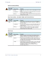
Table 19.
Hot Swap LED Reference
Indication
Recommended Action
Blue hot-swap LED is unlit
Ensure the card is fully seated and the ejector handles are
completely locked.
Verify power is getting to the chassis.
Blue hot-swap LED is on solid
Ensure the ejector handles are completely seated and locked.
Verify the Shelf Manager is properly installed.

