Selenio
TM
VMG-14+ Hardware Setup Guide
46
Installation Instructions
Gen2 Release 1.4.0
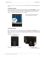
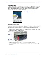
Figure 31.
AC Power Supply Unit: Ejector/Insertion Lever (Close)
4.
Insert the thumb screw and turn clockwise to tighten it.
AC
Power
Entry
Modules
(PEMs)
Four AC PEMs are installed at the chassis rear, which contains sockets for up to four Imagine
Communications power cords.(
).
Figure 32.
AC Power Entry Modules with Imagine Communications-Supplied Cords
AC
Power
Cord
Use only the AC power cords provided by Imagine Communications. Insert one into each applicable AC
PEM socket and plug it into the dedicated wall outlet near the installation rack. There are no circuit
breakers or ON/OFF switches. AC power is applied to the system directly from the site source.
Thumbscrew
Lever Up
(Closed)
REAR
Imagine Communications power cords for VMG-14+ AC systems

