8-11
FOCUS-VR
(UPPER SIDE)
SCREEN-VR
(LOWER SIDE)
VR661
+B ADJ
+B
TP601
J371
GND
PIN 15
OF CN902
WF18
PIN 18
OF CN902
WF19
PIN 19
OF CN902
WF20
PIN 20
OF CN902
WF21
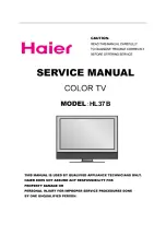
BL4800F01012-1
Main CBA Top View
For continued protection against risk of fire,
replace only with same type 4 A, 125V fuse.
CAUTION ! :
ATTENTION :
Utiliser un fusible de rechange de m
ê
me type de 4A, 125V.
4A/125V
CAUTION !
Fixed voltage (or Auto voltage selectable) power supply circuit is used in this unit.
If Main Fuse (F601) is blown , check to see that all components in the power supply
circuit are not defective before you connect the AC plug to the AC power supply.
Otherwise it may cause some components in the power supply circuit to fail.
NOTE:
The voltage for parts in hot circuit is measured using
hot GND as a common terminal.
Because a hot chassis ground is present in the power
supply circuit, an isolation transformer must be used.
Also, in order to have the ability to increase the input
slowly,when troubleshooting this type power supply
circuit, a variable isolation transformer is required.
Summary of Contents for IWF2706
Page 1: ...SERVICE MANUAL 27 ANALOG DIGITAL PURE FLAT COLOR TELEVISION IWF2706...
Page 34: ...8 3 Main 1 5 Schematic Diagram L4803SCM1...
Page 35: ...8 4 L4803SCM2 Main 2 5 Schematic Diagram...
Page 36: ...8 5 Main 3 5 Schematic Diagram L4803SCM3...
Page 37: ...8 6 L4803SCM4 Main 4 5 CRT Schematic Diagram...
Page 40: ...8 9 Digital 2 3 Schematic Diagram L4803SCD2...
Page 60: ...IWF2706 L4803UD 2006 03 10...