


1-2
P71D0SP
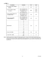
< ATSC >
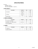
Note:
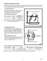
Nominal specifications represent the design specifications. All units should be able to approximate these.
Some will exceed and some may drop slightly below these specifications. Limit specifications represent the
absolute worst condition that still might be considered acceptable. In no case should a unit fail to meet limit
specifications.
Description
Condition
Unit
Limit
1. RECEIVED FREQ. RANGE
(-28dBm)
+
kHz
>100
–
2. ATSC DYNAMIC RANGE
(min./max.)
VHF LOW BAND. CH.4
dBm
-76/0
VHF HI BAND. CH.10
-76/0
UHF BAND. CH.41
-74/4
3. ATSC SUSCEPTIBILITY TO
RANDOM NOISE
VHF LOW BAND. CH.4
dB
<26
VHF HI BAND. CH.10
UHF BAND. CH.41
4. NTSC CO-CHANNEL
INTERFERENCE
VHF LOW BAND. CH.4
dB
>-6
VHF HI BAND. CH.10
UHF BAND. CH.41
5. MULTIPATH
A
dB
<6
B
C
D
E
F
FF
G
6. Audio S/N (0dBfs)
Lch
dB
>45
Rch
7. Audio DIST. (0dBfs)
Lch
%
<3
Rch
Summary of Contents for CR320IL8 A
Page 1: ...SERVICE MANUAL 32 DIGITAL ANALOG COLOR TELEVISION CR320IL8 A ...
Page 34: ...8 3 Main 1 5 Schematic Diagram P71D0SCM1 ...
Page 35: ...8 4 P71D0SCM2 Main 2 5 Schematic Diagram ...
Page 36: ...8 5 Main 3 5 Schematic Diagram P71D0SCM3 ...
Page 37: ...8 6 P71D0SCM4 Main 4 5 CRT Schematic Diagram ...
Page 39: ...8 8 DTV Module 1 2 Schematic Diagram P71D0SCD1 ...
Page 49: ...12 2 P71D0PEX Packing S4 S1 Tape X1 X3 FRONT X2 S2 S2 S3 S7 S6 Packing tape Packing tape ...