
3. Installing the Open Hole
Please refer to the opening hole drawing and drill the correct holes on the door.
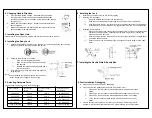
4. Installing the Body Lock
a.
Choose the installation direction of the latch-bolt of the lock body by the door opening
directions. (Refer to the images above and below)
b.
Changing the direction of lock body:
i.
Push the reversing block upwards.
ii.
Push the latch bolt into the body and twist
180 degrees.
iii.
Release the latch bolt and push back down
the reversing block.
c.
Put the lock body into the door frame and tighten 2
fixing screws.
Note:
•
When releasing the latch bolt, ensure the centre anti
friction tongue is not caught in the body lock.
5. Selecting Hardware Parts
Choose suitable parts according to the following table.
Door Thickness
Square Steel
Length
Connection Column
Length
Connection Column
Screw Length
39.8-54.8mm
80.0mm
35.0mm
29.9 and 50.0mm
55.1-59.9mm
80.0mm
55.1mm
29.9 and 50.0mm
60.1-80.0mm
100.0mm
55.1mm
50.0 and 70.1mm
80.1-10.00mm
119.8mm
55.1mm
70.1 and 89.9mm
>
100mm (optional)
139.9mm
55.1mm
89.9 and 109.9mm
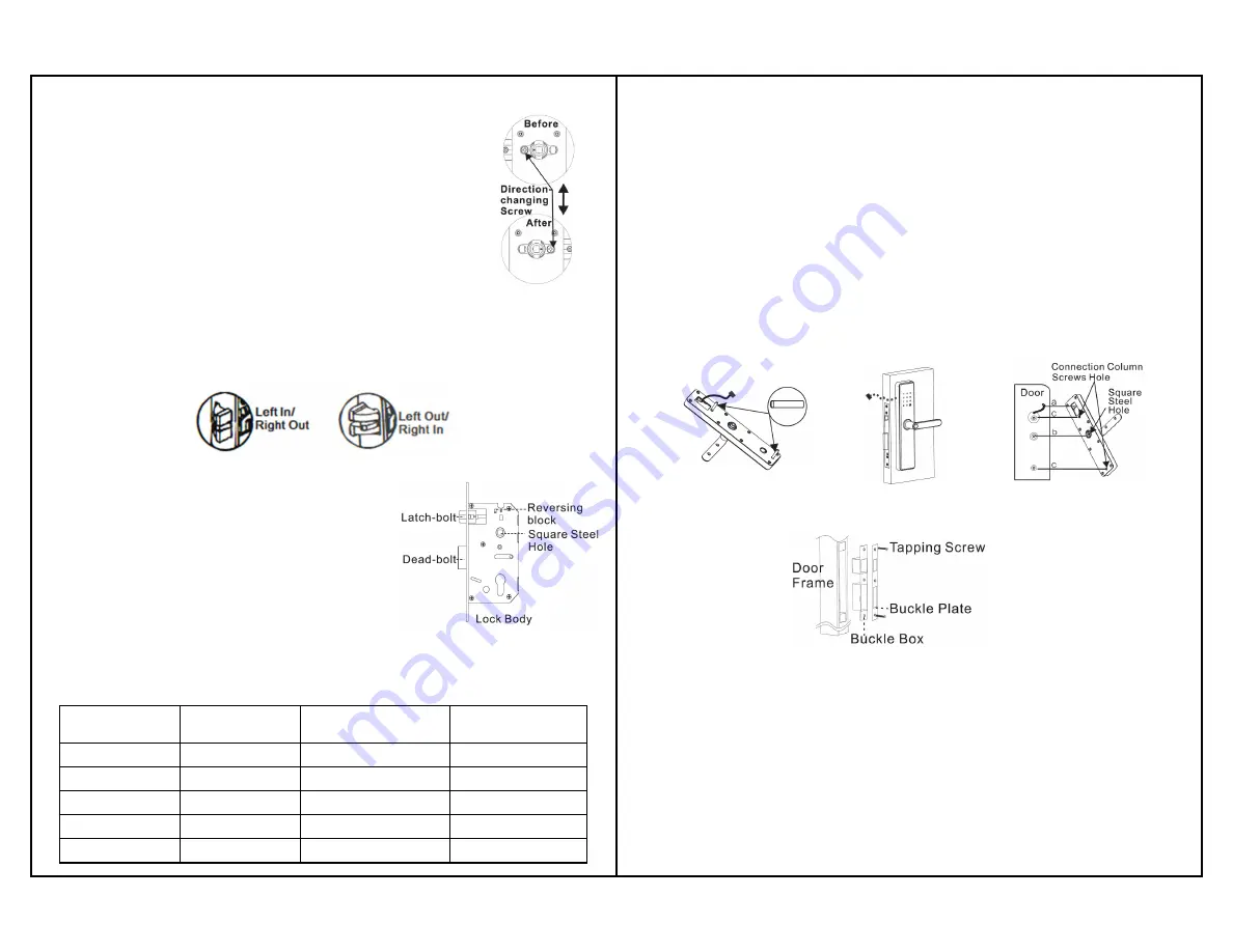
6. Installing the Lock
a.
Install two connection columns into the front panel
b.
Installing the front panel:
i.
Insert the suitable square steel into the lock body.
ii.
Pass the connection power line through the connection column screw hole.
iii.
Align the square steel on the lock body with the square steel hole of the front panel
and fix the front panel onto the door by pressing the other end of the square steel.
c.
Installing the back panel:
i.
Press the front panel and connect the connection power line with the corresponding
interface on the back panel. Cable manage the remaining wires by inserting the
excess line into the door hole.
ii.
Align the square steel on the body lock with the square steel hole of the back panel
and attach the back panel.
iii.
Secure the door lock by screwing in the 2-connection column screws on the back
panel
7. Installing the Buckle Plate & Buckle Box
8. Post Installation Debugging
a.
Always keep the door open when debugging.
b.
Check whether the following functions can be achieved or not.
i.
Press down the front handle, latch-bolt/dead-bolt remains still in locked
status.
ii.
Press down the front handle, latch-bolt/dead-bolt retract when unlocked.
iii.
Press down the back handle, latch-bolt/dead-bolt retract in any status.
iv.
Lift up the front handle or back handle, dead-bolt stretches out in any
status.
c.
Verify whether other functions are normal or not, including Self-locking, virtual
password, ‘Set’ button, Pickproof alarm, APP etc by referring to the user manual.
2. Changing Handle Direction
a.
Front Handle Direction Change – Disassemble the direction
changing screw and twist the hand downwards 180 degrees
carefully and slowly. Once in position, screw the direction change
screw back on.
b.
Back Handle Direction Change – Repeat the same operation as
above (step 2a).
c.
Match the front handle and back handle and make sure they are
both orientated in the same direction.


