background image

Draco vario

 DisplayPort


1.2


Maintenance


89 

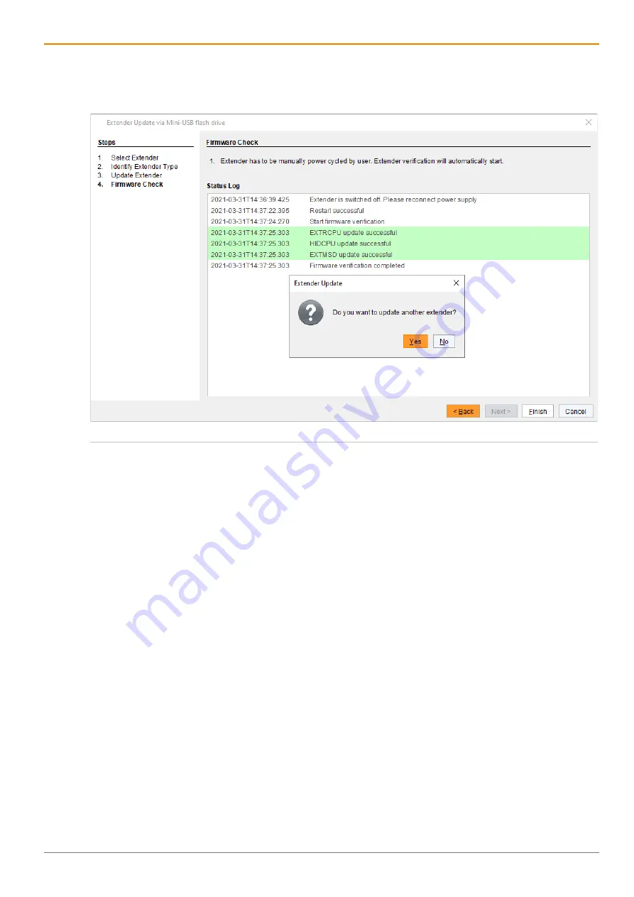
The firmware update of the extender module is completed. 
A dialog appears offering to update another extender module. 

18. Click 

Yes

 to update another extender module or click 

No

 and 

Finish

 to quit the Update dialog. 


Fig. 84 

Management software 

Flash Update - Firmware Check - Complete firmware update


Summary of Contents for Draco vario ultra DisplayPort 1.2

Page 1: ...Document 490_REV01 00_en Edition 2022 01 07 USER MANUAL Draco vario DisplayPort 1 2 KVM Extender Series 490 ...

Page 2: ...early described Please note the change log for this manual in chapter 17 page 128 The manufacturer reserves the right to change specifications functions or circuitry of the series described here without notice Information in this manual can be changed expanded or deleted without notice You can find the current version of the manual in the download area of our website Copyright 2022 All rights rese...

Page 3: ...tallation with Add on Module Audio 22 4 4 3 Dual Head Installation with Add on Module USB 2 0 23 4 5 Overview Add on Modules 24 4 6 Product Types 25 4 6 1 Chassis 25 4 6 2 Extender Modules without Local Input Output 25 4 6 3 Extender Modules with Local Input Output 26 4 6 4 Supplementary with Extended Function for Extender Modules 26 4 6 5 Add on Modules 26 4 6 6 Fan Cartridge Module 28 4 6 7 Add ...

Page 4: ...4 BAP 42 4 14 7 Add on Module Analog Audio bidirectional L R474 BAE BRE BSE 43 4 14 8 Add on Module Analog Audio bidirectional L R474 BAE2 BRE2 BSE2 43 4 14 9 Add on Module Analog Audio bidirectional L R474 BAH BSH 43 4 14 10 Add on Module Digital Audio unidirectional L R474 BDX 44 4 14 11 Add on Module Digital Audio unidirectional L R474 BDD 44 4 14 12 Add on Module Digital Audio unidirectional L...

Page 5: ...ess Option 64 5 1 Command Mode 65 5 2 Management Software 66 6 Installation 67 6 1 Setting up the System 67 6 1 1 Setting up the Extender Module 67 6 1 2 Setting up an Add on Module 68 6 2 Connecting to the Extender Module via Management Software 70 6 2 1 Connecting the Extender Module to the Computer 70 6 2 2 Starting the Management Software 71 7 Configuration 72 7 1 Configuration Options via Min...

Page 6: ...les via Copy Paste 90 10 2 3 Updating the Firmware of Add on Modules 92 10 3 Resetting an Extender Module to the Factory Settings 93 11 Troubleshooting 94 11 1 General Failures 94 11 2 Extender Module 94 11 2 1 Blank Screen 94 11 2 2 No USB HID Connection 95 11 3 Add on Modules 96 11 3 1 Serial Interface 96 11 3 2 Add on Module Analog Audio 97 11 3 3 Add on Module Digital Audio 97 11 3 4 Add on Mo...

Page 7: ...3 14 D Sub 9 GPIO 115 12 3 15 3 5 6 35 mm Stereo Jack Plug 115 12 3 16 RCA Cinch 115 12 3 17 Mini XLR 115 12 3 18 Toslink 116 12 3 19 Power Supply Voltage 116 12 4 Power Supply Voltage Current Draw and Power Consumption 117 12 4 1 Power Supply Voltage of the Chassis AC 117 12 4 2 Power Supply Voltage of the Chassis DC 117 12 4 3 Current Draw of the KVM Extenders Modules Series 490 117 12 4 4 Curre...

Page 8: ...Table of Contents Draco vario DisplayPort 1 2 8 14 3 WEEE 122 15 Glossary 123 16 Table of Figures 125 17 Change Log 128 ...

Page 9: ...TICE identifies information if not observed endangers the functionality of your device or the security of your data This symbol indicates information about special features on the device or when using device and function variants This symbol indicates instructions for procedures recommended by the manufacturer for an effective utilization of the device potential 1 3 Terms and Spellings Uniform ter...

Page 10: ...tions Mouse button Description Left mouse button Primary mouse button default in most operating systems Right mouse button Secondary mouse button Unless you have customized your mouse settings in the used operating system Descriptions containing click mouse click or double click each means a click with the primary left mouse button If the right mouse button has to be used this is explicitly declar...

Page 11: ...ly heated chassis surface after a long period of operation When the chassis is fully equipped the surface of the chassis can become very warm after a long period of operation If the chassis surface is touched after a long period of operation this can cause skin burns Protective gloves must be worn to transport a fully equipped chassis after a long period of operation Ensure that there is sufficien...

Page 12: ...ly units to grounded outlets Ensure that the ground connection is maintained from the outlet socket through to the power supply unit s AC power input Only connect the device to KVM devices using the interconnecting cable not to other devices particularly not to telecommunications or network devices Disconnect the Device from the Circuit NOTICE The cable plugs on the device side can contain a lock ...

Page 13: ...nts sont susceptibles d être présents ATTENTION Risque de brûlures dues à la surface du châssis très chaude après une longue période d utilisation Lorsque le châssis est entièrement équipé la surface du châssis peut devenir très chaude après une longue période de fonctionnement Si la surface du châssis est touchée après une longue période d utilisation cela peut provoquer des brûlures de la peau D...

Page 14: ...ges visibles au niveau du châssis ou du câble Connectez tous les unités d alimentation à des prises de terre Raccordez tous les unités d alimentation à des prises de courant mises à la terre Veillez à ce que la connexion à la terre soit maintenue depuis la prise de courant jusqu à l entrée d alimentation CA du les unités d alimentation Ne connectez le périphérique qu à des périphériques KVM à l ai...

Page 15: ...tions can also be used with applications in environments which are subject to electromagnetic interference NOTICE Interferences when the immunity limit values are exceeded If the limit values listed in EN55024 are exceeded reliable and fault free functioning of the devices cannot be guaranteed NOTICE Possible radio interference in a domestic environment This is a Class A product In a domestic envi...

Page 16: ...right see Fig 1 Fig 1 KVM Extender pair with CPU Unit and CON Unit 1 KVM Extender pair 2 Extender module or add on module optional 3 Extender module 4 Part A of the CPU add on module optional 5 Part B of the CPU add on module optional 6 Chassis 7 CPU Unit 8 Interconnect cable 9 CON Unit 10 Part A of the CON add on module optional 11 Part B of the CON add on module optional 12 Chassis 13 Extender m...

Page 17: ... CON Unit transferred to the add on module above and output there separately Example with optional Add on Module L R474 BAE Fig 4 Embedding de embedding of signals in a KVM extender pair example L R474 BAE 1 Source 2 Video signal with embedded audio signal 3 USB HID signal 4 Embedding the audio and USB 2 0 signal 5 Interconnect cable 6 De embedding the audio and USB 2 0 signal 7 USB HID signal 8 V...

Page 18: ... for the CON Unit required Fig 5 De embedding of audio signals in a KVM extender pair example R474 BDX 1 Source 2 Video signal with embedded audio 3 USB HID signal 4 Interconnect cable 5 De embedding digital audio signal 6 USB HID signal 7 Video signal with embedded audio 8 Sink console with monitor keyboard mouse and speakers 9 De embedded digital audio signal 2 3 4 2 3 1 9 5 6 8 7 ...

Page 19: ...X X X X X X X X L483 SH X X X X X X X X X X DH X X X X X X X X X X L484 SH X X X X X X X X X X L486 DH X X X X X X X X X X L490 SH X X X X X L491 SH X X X X X L492 SH X X X X X L493 SH X X X X X DH X X X X X L494 SH X X X X X L495 SH X X X X X 1 Compatibility is based on video USB HID signal only not on the embedded signals like audio or USB 2 0 2 Compatible up to the maximum specified resolution ...

Page 20: ...d on modules Extender modules of HDMI 1 3 series 481 491 and DP 1 1 series 483 493 support 5 1 channel digital audio whereas extender modules of HDMI 2 0 series 495 and DP 1 2 series 490 only support 2 channels Requires an audio add on module on the CPU Unit or the CON Unit True embedded audio Connection is representing audio content only Analog audio add on modules are not necessarily audio compa...

Page 21: ...85 BX 485 BXX Cat X 1G Fiber 1G Fiber 3G Cat X 1G Compatible Compatible Not compatible Fiber 1G Compatible Compatible Not compatible Fiber 3G Not compatible Not compatible Compatible Connection of Extender Modules via Matrix Draco tera enterprise with Bridge Card Cat X 1G CON Unit Fiber 1G CON Unit Fiber 3G CON Unit Cat X 1G CPU Unit Compatible Compatible Compatible Fiber 1G CPU Unit Compatible Co...

Page 22: ...interconnect cables 4 4 1 Single Head Installation Fig 7 Installation example Single Head 1 Source 2 CPU Unit 3 Interconnect cable 4 CON Unit 5 Console monitor keyboard mouse 4 4 2 Single Head Installation with Add on Module Audio Fig 8 Installation example Single Head with add on module audio 1 Source 2 KVM Extender CPU Unit 3 Interconnect cable 4 KVM Extender CON Unit 5 Console monitor keyboard ...

Page 23: ...g 9 Installation example Dual Head with add on module USB 2 0 1 Source 2 KVM Extender CPU Unit 3 Interconnect cable 4 KVM Extender CON Unit 5 Console monitor keyboard mouse 6 Second monitor optional only with Dual Head extenders 7 USB 2 0 devices optional only with add on modules USB 2 0 1 2 3 4 5 6 7 ...

Page 24: ...escription Draco vario DisplayPort 1 2 24 4 5 Overview Add on Modules This section illustrates an overview of the available types of add on modules for KVM extender modules Fig 10 Overview add on modules ...

Page 25: ...1x external Slide in Chassis Chassis Power supply unit Type Slots Active backplane Current input Internal External Setup for redundant power supply voltage 474 BODY2BPF 2 Yes Interface side 1x 1x external 474 BODY6BP 6 Yes Rear view 2x 474 BODY6BPF 6 Yes Interface side 2x 474 BODY21 4U 21 Yes Rear view 1x 1x internal 474 BODY21 4UR 21 Yes Rear view 2x All external power supply units are separately...

Page 26: ...to the SNMP manual Part number Description 474 SNMP SNMP module for sliding in into the chassis 474 BODY6BP slot 5 474 BODY6BPF slot 5 and 474 BODY21 4U slot 21 The transmission of the traps is unencrypted SNMP v1 474 SNMPV3 SNMP module for sliding in into the chassis 474 BODY6BP slot 5 474 BODY6BPF slot 5 and 474 BODY21 4U slot 21 The transmission of the traps is unencrypted SNMP v3 Extender modu...

Page 27: ...nd RS232 up to 115 k serial R474 BRX L474 BRE Add on module with analog audio bidirectional RS232 up to 115 k serial and 2x USB 2 0 embedded up to 36 Mbit s R474 BRE L474 BRE2 Add on module with analog audio bidirectional RS232 up to 115 k serial and 4x USB 2 0 embedded up to 50 100 Mbit s R474 BRE2 Add on Modules Analog Audio bidirectional RS422 serial Part No Description L474 BSX Add on module w...

Page 28: ... Analog Audio Part No Description L474 BBX Add on module with balanced analog audio unidirectional R474 BBX L474 BBE2 Add on module with balanced analog audio unidirectional and 4x USB 2 0 embedded up to 50 100 Mbit s R474 BBE2 Add on Modules GPIO Part No Description R474 BGX Add on module for CON Units with up to 8 configurable GPIO in outputs R474 BGE2 Add on module for CON Units with up to 8 co...

Page 29: ...Spare PSU for 474 BODY21 4U slide in hot swap 474 BLND1 Blanking plate with IHSE Logo 1 slot for Draco vario chassis 474 6FAN Optional fan for Draco vario 2 slot and 6 slot chassis with backplane 260 5G International power supply unit 100 240VAC 5VDC 3A 260 5M International power supply unit 100 240VAC 5VDC 5A PC TYP E C13 020 Power cord IEC Schuko 90 Type E C13 2 0 m lockable PC TYP B C13 020 Pow...

Page 30: ...CT TOSLINK cable 2 0 m Audio 247 U1 USB cable Type A B 1 8 m USB USB HID 247 U2 USB cable Type A B 3 0 m USB USB HID 436 USB20 USB extension cable Type A A 3 0 m USB USB HID 024 3A PS 2 cable 1 8 m USB USB HID DC DB9 MF 018 RS 232 422 data cable DB9 male female 1 8 m Serial 476 CTRL4 GPIO Remote Control for Draco vario GPIO module with 4 push buttons LEDs cable length approx 3 0 m GPIO ...

Page 31: ... 474 BODY4 474 BODY4R 1x 5 V DC 5 A international power supply unit 1x country specific power cord 474 BODY2N 474 BODY2BPF 474 BODY6R R1 1x IEC country specific power cord C13 2 0 m 474 BODY6BP 474 BODY6BPF 474 BODY21 4UR 2x IEC country specific power cord C13 2 0 m lockable 474 BODY21 4U 1x IEC country specific power cord C13 2 0 m lockable 4 10 2 Scope of Delivery Add on Modules Some add on modu...

Page 32: ...is see chapter 12 4 page 117 and chapter 12 4 2 page 117 The device status of a module is displayed via LED on the front side of following chassis 474 BODY2 474 BODY2R 474 BODY2N 474 BODY4 474 BODY4R and 474 BODY6R R1 4 11 1 2 Slot Chassis Draco vario 474 BODY2 Fig 11 Interface side chassis 474 BODY2 1 Slot 1 2 Slot 2 3 Power supply voltage DC 4 11 2 2 Slot Chassis Draco vario 474 BODY2R Fig 12 In...

Page 33: ...Excessive current draw The 2 slot Draco vario chassis with an internal power supply unit is not equipped with a fuse on its primary side The protection against excessive current draw has to be provided by the electrical installation of the building 4 11 4 2 Slot Chassis Draco vario 474 BODY2BPF Fig 14 Interface side chassis 474 BODY2BPF 1 Slot 1 2 Slot 2 3 Power supply voltage 2 DC 4 Power supply ...

Page 34: ...ODY4 Fig 15 Interface side chassis 474 BODY4 1 Slot 1 2 Slot 2 3 Slot 3 4 Slot 4 5 Power supply voltage DC 4 11 6 4 Slot Chassis Draco vario 474 BODY4R Fig 16 Interface side chassis 474 BODY4R 1 Slot 1 2 Slot 2 3 Slot 3 4 Slot 4 5 Power supply voltage 2 DC 6 Power supply voltage 1 DC ...

Page 35: ...upply unit fails the device s power supply voltage is secured via the 5 V external power supply unit If there is no redundant power supply voltage and the current is above 5 A the device is not supplied with sufficient power supply voltage and fails Note the maximum current draw of the chassis see from chapter 12 4 page 117 With a current of more than 5 A use an external power supply unit In this ...

Page 36: ...ot 2 3 Slot 3 4 Slot 4 5 Slot 5 6 Slot 6 Fig 19 Rear view chassis 474 BODY6BP 1 Power supply voltage 1 AC 2 Power supply voltage 2 AC 3 Grounding 4 11 9 6 Slot Chassis Draco vario 474 BODY6BPF Fig 20 Interface side chassis 474 BODY6BPF 1 Slot 1 2 Slot 2 3 Slot 3 4 Slot 4 5 Slot 5 6 Slot 6 7 Power supply voltage 1 AC 8 Power supply voltage 2 AC ...

Page 37: ...left to right The chassis 474 BODY21 4U is supplied with one power supply unit Pos 3 A second power supply unit can be optionally installed The chassis 474 BODY21 4UR is supplied with two power supply units Pos 2 and 3 Fig 22 Rear view chassis 474 BODY21 4U and 474 BODY21 4UR 1 Power supply voltage 2 AC redundancy 2 Power supply unit 2 redundancy 3 Power supply unit 1 4 Power supply voltage 1 AC ...

Page 38: ...nnection 3 USB Type A USB HID device 1 4 USB Type A USB HID device 2 5 DisplayPort 1 2 output to monitor 4 12 2 Extender Module L R490 BPHXR Source side CPU module Sink side CON module Fig 24 Interface side L R490 BPHXR 1 Mini USB service interface 2 Fiber interconnection 1 3 Fiber interconnection 2 4 USB Type B USB HID 5 DisplayPort 1 2 input source 1 Mini USB service interface 2 Fiber interconne...

Page 39: ...device 2 5 DisplayPort 1 2 output to monitor 6 Mini DisplayPort 1 2 local input 4 13 2 Extender Module L R490 BPHCXLR Source side CPU module Sink side CON module Fig 26 Interface side L R490 BPHCXLR 1 Mini USB service interface 2 Cat X interconnection 1 3 Cat X interconnection 2 4 Input Output Cat X interconnection 2 5 USB Type B USB HID 6 DisplayPort 1 2 input source 7 Mini DisplayPort 1 2 local ...

Page 40: ... DisplayPort 1 2 output to monitor 6 Mini DisplayPort 1 2 local input 4 13 4 Extender Module L R490 BPHXLR Source side CPU module Sink side CON module Fig 28 Interface side L R490 BPHXLR 1 Mini USB service interface 2 Fiber interconnection 1 3 Fiber interconnection 2 4 USB Type B USB HID 5 DisplayPort 1 2 input source 6 Mini DisplayPort 1 2 local output 1 Mini USB service interface 2 Fiber interco...

Page 41: ...e USB 2 0 embedded L R474 BXE2 Source side CPU module Sink side CON module Fig 30 Interface side L R474 BXE2 1 USB Type B USB 2 0 up to 50 100 Mbit s 1 USB Type A USB 2 0 up to 50 100 Mbit s 2 USB Type A USB 2 0 up to 50 100 Mbit s 3 USB Type A USB 2 0 up to 50 100 Mbit s 4 USB Type A USB 2 0 up to 50 100 Mbit s 4 14 3 Add on Module USB HID L R474 BXH Source side CPU module Sink side CON module Fi...

Page 42: ...o output 4 D Sub 9 female socket RS422 serial 5 3 5 mm jack socket analog audio input 6 3 5 mm jack socket analog audio output 1 D Sub 9 female socket RS422 serial 2 3 5 mm jack socket analog audio input 3 3 5 mm jack socket analog audio output 4 D Sub 9 female socket RS422 serial 5 3 5 mm jack socket analog audio input 6 3 5 mm jack socket analog audio output 4 14 6 Add on Module Analog Audio bid...

Page 43: ...l 2 3 5 mm jack socket analog audio input 3 3 5 mm jack socket analog audio output 4 USB Type B USB 2 0 up to 50 100 Mbit s 1 D Sub 9 male socket RS232 serial 2 3 5 mm jack socket analog audio input 3 3 5 mm jack socket analog audio output 4 USB Type A USB 2 0 up to 50 100 Mbit s 5 USB Type A USB 2 0 up to 50 100 Mbit s 6 USB Type A USB 2 0 up to 50 100 Mbit s 7 USB Type A USB 2 0 up to 50 100 Mbi...

Page 44: ... XLR AES EBU input 6 TOSLINK S PDIF input 1 RCA S PDIF output 2 Mini XLR AES EBU output 3 TOSLINK S PDIF output 4 RCA S PDIF output 5 Mini XLR AES EBU output 6 TOSLINK S PDIF output 4 14 12 Add on Module Digital Audio unidirectional L R474 BDA Source side CPU module Sink side CON module Fig 40 Interface side L R474 BDA 1 RCA S PDIF input 2 Mini XLR AES EBU input 3 TOSLINK S PDIF input 4 D Sub 9 fe...

Page 45: ...e L R474 BDE2 1 RCA S PDIF input 2 Mini XLR AES EBU input 3 TOSLINK S PDIF 4 USB Type B USB 2 0 up to 50 100 Mbit s 1 RCA S PDIF output 2 Mini XLR AES EBU output 3 TOSLINK S PDIF output 4 USB Type A USB 2 0 up to 50 100 Mbit s 5 USB Type A USB 2 0 up to 50 100 Mbit s 6 USB Type A USB 2 0 up to 50 100 Mbit s 7 USB Type A USB 2 0 up to 50 100 Mbit s 4 14 15 Add on Module Digital Audio unidirectional...

Page 46: ...udio L R474 BBE2 Source side CPU module Sink side CON module Fig 45 Interface side L R474 BBE2 1 Switch for phantom power 2 6 35 mm jack socket analog audio input 1 3 6 35 mm jack socket analog audio input 2 4 Dip switch for pre amplification 5 USB Type B USB 2 0 up to 50 100 Mbit s 1 6 35 mm jack socket analog audio output 1 2 6 35 mm jack socket analog audio output 2 3 Not in use 4 USB Type A US...

Page 47: ...o 50 100 Mbit s 3 USB Type A USB 2 0 up to 50 100 Mbit s 4 USB Type A USB 2 0 up to 50 100 Mbit s 5 USB Type A USB 2 0 up to 50 100 Mbit s 4 14 20 Fan Cartridge Module 474 MODFAN The fan cartridge module 474 MODFAN can be installed in all slots of the chassis For optimal ventilation we recommend installation of the fan cartridge module in the upper slots of the chassis Fig 48 Interface side 474 MO...

Page 48: ...to 50 100 Mbit s 4 USB Type A USB 2 0 up to 50 100 Mbit s 5 USB Type A USB 2 0 up to 50 100 Mbit s 6 USB Type A USB 2 0 up to 50 100 Mbit s 4 15 2 Add on Module Extender Module USB 2 0 Stand alone L R474 BXUS Source side CPU module Sink side CON module Fig 50 Interface side L R474 BXUS 1 Mini USB service interface 2 Fiber interconnection 3 USB Type B USB 2 0 up to 50 100 Mbit s 1 Mini USB service ...

Page 49: ...ly voltage available Off No power supply voltage available 4 16 2 2 Slot Chassis Draco vario 474 BODY2R Fig 52 Interface side chassis 474 BODY2R Status LEDs 1 LED for power supply voltage 1 2 LED for power supply voltage 2 Status LEDs for Power Supply Voltage The following tables show the LED states colors for the power supply voltage see chapter 4 11 2 page 32 for the respective situation Pos 1 P...

Page 50: ...supply voltage available Red Green No redundant power supply voltage available Off Off No power supply voltage available 4 16 4 2 Slot Chassis Draco vario 474 BODY2BPF Fig 54 Interface side chassis 474 BODY2BPF Status LEDs 1 LED for power supply voltage 1 2 LED for power supply voltage 2 Status LEDs for Power Supply Voltage The following tables show the LED states colors for the power supply volta...

Page 51: ...able Off No power supply voltage available 4 16 6 4 Slot Chassis Draco vario 474 BODY4R Fig 56 Interface side chassis 474 BODY4R Status LEDs 1 LED for power supply voltage 1 2 LED for power supply voltage 2 Status LEDs for Power Supply Voltage The following tables show the LED states colors for the power supply voltage see chapter 4 11 6 page 34 for the respective situation Pos 1 Pos 2 Description...

Page 52: ...wer supply voltage available Red Green No redundant power supply voltage available Off Off No power supply voltage available 4 16 8 6 Slot Chassis Draco vario 474 BODY6BP Fig 58 Interface side chassis 474 BODY6BP Status LEDs 1 LED for power supply voltage 1 2 LED for power supply voltage 2 Status LEDs for Power Supply Voltage The following tables show the LED states colors for the power supply vol...

Page 53: ...1 LED for power supply voltage 1 2 LED for power supply voltage 2 Status LEDs for Power Supply Voltage The following tables show the LED states colors for the power supply voltage see chapter 4 11 9 page 36 for the respective situation Pos 1 Pos 2 Description Green Green Redundant power supply voltage available Green Red No redundant power supply voltage available Red Green No redundant power supp...

Page 54: ...e chapter 4 11 10 page 37 for the respective situation Pos 3 Pos 4 Description Green Off Power supply voltage available Green Red The input voltage of the power supply unit is too low The output voltage of the power supply unit too high Permissible power supply temperature exceeded Off Off No power supply voltage available Status LEDs for Power Supply Voltage of the Redundant Power Supply Unit Pos...

Page 55: ...LED 1 3 and right LED 2 4 of the CPU Unit and the CON Unit for the respective situation Pos 1 3 Pos 2 4 Description Off Green Link connection available Off Flashing green No link connection available Flashing green Green Link connection failure flashes for approx 20 s following each occurring connection failure Link Connection Fiber 1G and 3G The following table shows the respective Link LED state...

Page 56: ... a video signal is present at which resolution a video signal is transmitted or whether a USB connection exists The following tables show the respective LED states colors upper LED 2 and the lower LED 1 of the CPU Unit column 2 and the CON Unit column 3 for the respective situation Without Link Connection without Video Signal Pos LED CPU Unit LED CON Unit 2 Red Flashing red violet 1 Red Flashing r...

Page 57: ... LED CPU Unit LEDCON Unit Effective data rate 2 Violet Flashing red violet Max 4 14 Gbit s 1 Light blue Flashing green light blue 2 Light blue Flashing green light blue Between 4 14 and 17 28 Gbit s 1 Light blue Flashing green light blue With Link Connection Video Signal and USB Connection Pos LED CPU Unit LEDCON Unit Effective data rate 2 Violet Violet Max 4 14 Gbit s 1 Light blue Light blue 2 Li...

Page 58: ... Sink side CON module Fig 64 Interface side add on module digital audio Status LEDs 1 Status LED digital audio 1 Status LED digital audio Pos LED Status Description 1 Red Static CPU Unit and CON Unit no signal Light blue Static CPU Unit S PDIF signal RCA available Flashing CPU Unit digital noise Violet Static CPU Unit AES EBU signal Mini XLR available Flashing CPU Unit digital noise Blue Static CP...

Page 59: ...B HID device 1 status LED 2 USB HID device 2 status LED 3 Link status LED 1 USB HID device 1 status LED 2 USB HID device 2 status LED 3 Link status LED The following tables show the respective LED states colors of the CPU add on module column 2 and the CON add on module column 3 for the respective situation Pos LED CPU Add on LED CON Add on Description 1 Off Off Link connection between add on modu...

Page 60: ...ff Link connection between add on module and extender module and between CPU Unit and source available Keyboard connected to USB HID port 1 or 2 Keyboard input active 2 Red Red fast flashing 3 Red fast flashing Red fast flashing 1 Red Red fast flashing Link connection between add on module and extender module and between CPU Unit and source available Mouse connected to USB HID port 1 or 2 Mouse ac...

Page 61: ...d on module column 3 for the respective situation Pos LED CPU Add on LED CON Add on Description 1 Off Off Link connection between CPU Unit and CON Unit available No USB connection between CPU Unit and source available 2 Off Off 3 Green Green 1 Green flashing Green flashing Link connection between CPU Unit and CON Unit available USB connection between CPU Unit and source available 2 Green Green 3 G...

Page 62: ...dge module Status LEDs 1 Status LED Pos LED Color Description 1 Red Static Failure fan is not operable Green Static Fan runs with reduced speed until 40 C with parameter set see chapter 7 5 4 page 78 Light blue Static Operating condition The light blue LED is very bright and might also appear as white 1 ...

Page 63: ...ection Cat X Pos 1 Pos 3 Pos 2 Pos 4 Description Off Green Link connection available Off Flashing green No link connection available Flashing green Green Link connection failure flashes for approx 20 s following each occurring connection failure Status LEDs for Link Connection Fiber Pos 1 Pos 3 Pos 2 Pos 4 Description Off Green Link connection available Off Flashing red No link connection availabl...

Page 64: ...al extender module functions for USB HID Ghosting and the EDID as well as switching via command mode and additional keyboard commands can be executed Management software Firmware updates for extender modules can be performed via the management software The management software is available in the form of a single executable program file The management software can be downloaded from the link https ...

Page 65: ...mmands are used to enter and to exit the command mode and to change the Hot Key Function Keyboard command Start the command mode 2x Left Shift Hot Key factory setting Exit the command mode Esc and also Left Shift Esc if necessary Change the Hot Key current Hot Key c new Hot Key Code Enter NOTICE In a combined KVM matrix U switch configuration select different Hot Keys for the connected extender mo...

Page 66: ...ot Key on a German or US keyboard layout the French keyboard layout AZERTY requires then 2x q as Hot Key to be pressed instead Reset the Hot Key To set a Hot Key back to default settings press Right Shift Del within 5 s after switching on the CON Unit or plugging in a keyboard The Hot Key is set back to Left Shift 5 2 Management Software The menu structure of the management software is subdivided ...

Page 67: ...ect the monitor s keyboard and mouse to the CON Unit 2 Connect the CON Unit to the power supply unit s power socket s Installing the CPU Unit 1 Connect the source to the CPU Unit with the supplied cables Please ensure the cables are not strained 2 Connect the CPU Unit to the power supply unit s power socket s Establishing a Point to Point Connection of CON Unit and CPU Unit and Powering on the sys...

Page 68: ...tput of the CON Unit to suitable speakers or audio amplifiers If several active sources are connected Mini XLR input takes priority The audio signal is available at all outputs Add on Module Balanced Audio 1 Connect the balanced audio source to the appropriate audio input of the CPU Unit 2 Connect the audio output of the CON Unit to suitable speakers or audio amplifiers Add on Module USB HID 1 Con...

Page 69: ... the bottom input The DIP switches belong to the pins listed below Pin 1 Pin2 Pin 3 Pin 4 Pin 5 Pin 6 Pin 7 Pin 8 Pin 9 DIP Switch 1 2 3 4 5 6 7 8 To set up the GPIO add on module for an external keypad with up to four buttons and one associated LED each proceed as follows Move the DIP switches of the pins up ON output to which you want to connect LEDs Fig 71 Example of DIP switch settings ...

Page 70: ...0 Management software with integrated Java Runtime Tera Tool Downloaded from https www ihse com software If you want to use the management software without integrated Java Runtime the following requirements must be fulfilled Computer Software Network Requirements Recommendations Free memory RAM Recommended 512 MB Operating system Microsoft Windows 8 Windows 8 1 Windows 10 macOS macOS 10 14 Mojave ...

Page 71: ...io DisplayPort 1 2 Installation 71 6 2 2 Starting the Management Software Open the management software by a double click on the program icon on the desktop or the file in the directory Fig 72 Management software ...

Page 72: ...r using a mini USB cable the CPU Unit CON Unit is displayed in the computer s file manager as an external drive 401xxxxx or 101xxxxx Serial No This directory contains the configuration file Config txt the EDID and firmware files The Config txt file shows the Serial No the manufacturing p n and the video signal details If present additional configuration parameters are displayed in the line directl...

Page 73: ...med during normal operation see chapter 8 1 page 80 For special requirements the EDID can be retrieved and uploaded as a binary file to both the CPU Unit and the CON Unit Connect your computer with a Mini USB cable to the service port of the CPU Unit or CON Unit The data area of the CPU Unit or CON Unit is now accessible as a flash drive Extender Uploading the EDID Copy the binary file containing ...

Page 74: ...in the CPU Unit Hot Key h d Enter Deactivate the emulation of active device descriptions in the CPU Unit The input devices connected to the CON Unit will be now passed transparently to the source Hot Key h r Enter Deactivate the emulation of active device descriptions in the CPU Unit Deletes the descriptions out of the CPU Unit The input devices connected to the CON Unit will be now passed transpa...

Page 75: ...r or change a parameter of an extender module proceed as follows 1 Connect the extender module to any source using a Mini USB cable The extender module opens a flash drive containing the Config txt file 2 Open the Config txt file in a text editor 3 Ensure that CFG is written in the first line of the file 4 Add a line break directly behind CFG 5 Add the parameter s in capitals in the line below CFG...

Page 76: ...96000 Activate sample rate conversion sample rate 96 kHz only with digital audio add on module L490 SRC176400 Activate sample rate conversion sample rate 176 4 kHz only with digital audio add on module L490 SRC192000 Activate sample rate conversion sample rate 192 kHz only with digital audio add on module L490 SRC_NONE Deactivate sample rate conversion only with digital audio add on module L490 SR...

Page 77: ...or if the mentioned parameters are available for the complete series e g v Output Settings Parameter Function Series DISEXTOSD Deactivate extender module OSD R490 ENAFRAME Show orange colored frame when losing extender module connection R490 ENAHOLDPIC Show last transmitted picture highlighted by an orange colored frame when losing connection R490 ENALOSTMR Activate LOS timer R490 ENADDCTX Activat...

Page 78: ...ed add on modules only with add on module L474 R474 BXE not for L474 R474 BXE2 Needs to be set on CPU Unit and CON Unit mixed configurations not supported L490 R490 Transmission Parameter Function Series ENASYNC Activate a synchronization impulse to adjust the pixel clock between the CPU Unit and CON Unit L490 R490 7 5 4 Parameters for the Add on Module 474 MODFAN Parameter Function LOWSPEED Reduc...

Page 79: ...hat CFG is in the first line of the file 4 Activate the release timer by writing the parameter RELEASETIME n into the second line The variable n defines the time in seconds and has to be replaced by the numbers 0 to 9 e g RELEASETIME 5 If this parameter is not activated at all the release time is set to 2 seconds by default The parameter RELEASETIME X deactivates the shared operation 5 Delete ever...

Page 80: ... should be optimal The source should now show the console monitor as the current screen together with the available video resolutions If the EDID was loaded once the EDID can be reloaded by repeating the process Keyboard commands are fixed to the position of the keys on the keyboard Keyboard mapping tables may vary for country specific layouts E g press Hot Key q on a French keyboard layout AZERTY...

Page 81: ...of the Dual Head CPU Unit Hot Key d 2 Enter Switch to video channel 2 of the Dual Head CPU Unit 8 4 Switching of two different CPU Units via redundant CON Unit CON Units with a redundant port for interconnect cables offer the possibility to connect two different CPU Units with different sources To switch a redundant CON Unit with two different CPU Units proceed as follows Keyboard command Function...

Page 82: ...ommand Mode 9 1 1 Starting and Exiting the Command Mode Keyboard command Function 2x Left Shift Start the command mode Hot Key factory setting Esc Exit the command mode 9 1 2 Changing and Resetting the Hot Key Hot Key Keyboard command Function Hot Key c new Hot Key code Enter Change the Hot Key according to the predefined Hot Key Code table Hot Key c 0 new Hot Key Enter Define a freely selectable ...

Page 83: ...the CPU Unit The input devices connected to the CON Unit will be now passed transparently to the source 9 3 Switching 9 3 1 Switching of Sources for CON Units with local Input Keyboard command Function Hot Key k 1 Enter Switch to the extender module connection 1 Hot Key l Enter Switch to the local source For switching of redundant CON Units see chapter 8 4 page 81 9 3 2 Switching of Video Channels...

Page 84: ...service port Via management software see following chapter Via copy paste see chapter 10 2 2 page 90 NOTICE To process successful firmware updates and avoid failures For firmware update of the extender module use only stand alone computers that are not integrated into the extender module setup Ensure that the computer used for the firmware update is not set into standby mode or sleep mode during t...

Page 85: ...nt extender module to be updated in each running management software To perform a firmware update of extender modules using the management software proceed as follows 1 Run the management software 2 Click Flash Update in the toolbar 3 Click Extender Update via Mini USB flash drive Fig 76 Management software Flash Update The update dialog appears 4 Connect the extender module to your computer runni...

Page 86: ...nagement software Flash Update Select Extender The identification of the extender module type automatically starts After successful identification the extender module specific firmware is displayed in the Status Log area 9 Click Next after successful identification Fig 79 Management software Flash Update Identify Extender Type ...

Page 87: ...ect the update files and click Select in the selection dialog The firmware available for the extender module is displayed Firmware requiring any update will be automatically highlighted 12 Click Update to start the update process After the update of an MSD firmware the extender module will automatically be restarted Fig 81 Management software Flash Update Update Extender Load files ...

Page 88: ...are Flash Update Update Extender Firmware update completed 14 Click Next 15 Manually power off the extender module 16 Power on the extender module The extender module restarts and validation begins automatically The completion of the validation is displayed in the Status Log area Fig 83 Management software Flash Update Firmware Check Firmware verification completed 17 Click Finish ...

Page 89: ...the extender module is completed A dialog appears offering to update another extender module 18 Click Yes to update another extender module or click No and Finish to quit the Update dialog Fig 84 Management software Flash Update Firmware Check Complete firmware update ...

Page 90: ...this chapter NOTICE Possible update failure with extender modules of the Draco vario ultra Series 493 The extender modules of the Draco vario ultra Series 493 with firmware listed below require special handling of manual firmware updates These firmware files cannot be overwritten FZTDPCPU FZTDPCON FZVDPCPU FZVDPCON When updating an extender module of the Series 493 with one of these named firmware...

Page 91: ...an extender module via copy paste using the Mini USB service port proceed as follows 1 Connect the extender module to your computer via Mini USB cable The flash drive of the extender module opens 2 If you want to update an extender module of the 493 Series with any of the firmware mentioned above delete all firmware contained in the flash drive of the respective extender module 3 Navigate on your ...

Page 92: ...ceed as follows 1 Connect the USB 2 0 module to any source using a Mini USB cable The USB 2 0 module opens a flash drive containing the Config txt file 2 Delete the USB firmware on the flash drive 3 Manually power off the USB 2 0 module 4 Power on the USB 2 0 module The USB 2 0 module starts automatically 5 Copy the REX_xx pfw file to the USB 2 0 module 6 Manually power off the USB 2 0 module 7 Po...

Page 93: ... Config txt file 3 Manually power off the extender module 4 Power on the extender module The extender module restarts and the extender module s parameters such as Serial No the manufacturing p n and the video signal details are written in the Config txt file USB HID Ghosting 1 Reset the USB HID Ghosting by entering this keyboard command Hot Key h r Enter EDID 1 Connect the extender module to any s...

Page 94: ...ailure indication See also status display of the extender modules in chapter 4 17 from page 55 Diagnosis Possible reason Measure All LEDs are off Power supply voltage not available Check the power supply units Check the connection to the power network LED 1 3 or 2 4 are flashing No link connection between CON Unit and CPU Unit available Check the interconnect cables Check the connectors CON Unit L...

Page 95: ... CPU module Sink side CON module Fig 86 Interface side extender module USB HID Failure indication In the following diagnoses causes and measures are described for the case that a video signal is present See also status indication of the extender modules in chapter 4 17 from page 55 In the case of shared operation of a redundant CPU Unit control of the USB HID devices on the non active CON Unit can...

Page 96: ...20 px 1200 px The keyboard is in command mode Press Esc to leave the command mode Or press Left Shift Esc to leave the command mode Shared operation of a redundant CPU Unit Move the mouse or press a key to get back USB HID control Or press Left Shift Esc to leave the command mode CON Unit LED 1 is flashing green light blue and LED 2 is light blue resolution 1920 px 1200 px The keyboard is in comma...

Page 97: ...io source No audio connection to the audio sink e g computer available Check the connection of the audio cable between the CPU Unit and the audio sink Check the audio configuration 11 3 3 Add on Module Digital Audio CPU side CPU module Console side CON module Fig 1 Interface side add on module digital audio Failure indication Diagnosis Possible reason Measure CPU Unit LED 1 lights up red No audio ...

Page 98: ...D cable to the USB HID device Connect a USB HID device Contact your distributor if necessary The USB HID device is not supported Check the compatibility New connection of the USB HID device Contact your distributor if necessary No USB HID connection to the source available Check the connection of the USB cable to the source select another USB HID port if necessary Remove the USB and power cables f...

Page 99: ...he OSD USB 2 0 device without function No USB 2 0 device connected Check the cable to the USB 2 0 device Connect a USB 2 0 device Contact your distributor if necessary The USB 2 0 device is not supported Check the installation of the USB 2 0 device and the necessary drivers at the CPU New connection of the USB 2 0 device Contact your distributor if necessary USB 2 0 device without function CPU Uni...

Page 100: ...f the USB cable to the source select another USB port if necessary Remove the USB and power cables first connect the power cable then connect the USB cable and restart the CPU Unit LED 1 flashes Link connection failure between CON Unit and CPU Unit Check the interconnect cable Check the connectors LED 2 flashes No connection between CON Unit and CPU Unit available Check the interconnect cable Chec...

Page 101: ...ng 101 11 4 Fan Cartridge Module Fig 5 Interface side fan cartridge module Failure indication Diagnosis Possible reason Measure LED 1 red Fan is not operable Check the firmware version The fan is defect Contact your distributor if necessary 1 ...

Page 102: ...hrough the interface Parameter Value Standards Stereo Linear Pulse Code Modulation LPCM Bit depth 16 to 24 bit Sample rate 32 to 192 kHz 12 1 2 Mini DisplayPort 1 2 Upstream Downstream The pins of the Mini DisplayPort sockets are assigned differently Upstream data is sent e g source graphics card video output of a device Downstream data is received e g sink monitor video input of a device Video Th...

Page 103: ...ion cables cannot be guaranteed Only two USB HID devices are supported concurrently such as keyboard and mouse or keyboard and touch screen A hub is allowed but it does not increase the number of devices allowed To support other USB non HID devices such as scanners web cams or memory devices use the USB 2 0 interfaces 12 1 4 PS 2 Our devices with PS 2 interface support the use of a PS 2 keyboard a...

Page 104: ... SFPs provided by the manufacturer NOTICE SFP modules can be damaged by electrostatic discharge ESD Please consider ESD handling specifications 12 1 10 RS232 Serial Extender modules with serial interface option support a full duplex transmission with a real hardware handshake up to a baud rate of 115 200 Baud The CON Unit is cabled as DTE Data Terminal Equipment like CPU output and can be connecte...

Page 105: ...Serial Extender modules with a serial interface RS422 D Sub 9 support a differential full duplex transmission up to a baud rate of 115 200 Baud The CPU Unit is designed as controlling device and can for example be connected directly to video or media servers The CON Unit is designed as a controlled device and can be connected directly to remote controllers Parameter Value Connection Format Sony St...

Page 106: ...cted to the audio input of the sound card blue Choose this connection if the microphone has its own pre amplifier The CON Unit can also provide pre amplification of a microphone To activate the pre amplification Open the CON Unit Locate the pins marked with MICJP on the audio board and close the pins with a jumper Specification Analog Audio Parameter Value Transmission format Digitized virtually C...

Page 107: ... converter for the output by writing the parameter in a new line The following sample frequencies are available 32 0 kHz write SRC32000 in the Config txt file of the CPU Unit 44 1 kHz write SCR44100 in the Config txt 48 0 kHz writeSCR48000 in the Config txt file of the CPU Unit 96 0 kHz writeSCR96000 in the Config txt file of the CPU Unit You can set a delay for converting the sample rate The time...

Page 108: ...n only be activated on the audio input side CPU module The microphone has to be connected to the audio input of the CPU module To activate phantom power the switch on the CPU module has to be pressed and clicked into the pressed position NOTICE Damage to audio output devices from phantom power If audio output devices e g loudspeakers are operated with phantom power unexpected damage can occur to t...

Page 109: ...76400 in Config txt file 192 0 kHz enter SRC192000 in Config txt file Compatibility Extender modules with balanced audio interface are compatible to extender modules with digital audio interface regarding the transmission of the audio standard 2 channel PCM The compatibility shall be applied to the add on module digital audio and the extender modules of the 481 491 and 483 493 series The compatibi...

Page 110: ...ity The operation of the devices without mounted ferrites leads to a loss of conformity with the EU directives Mount ferrites on both sides of all Cat X cables near the device to maintain regulatory EMC compliance Type of Interconnect Cable The extender modules require interconnect cabling specified for Gigabit Ethernet 1000BASE T The use of solid core AWG24 shielded Cat 5e or better is recommende...

Page 111: ...fibers 50 μm I V ZN H 2G50 in house patch cable I AD ZN H 4G50 in house or outdoor breakout cable resistant Cable notations according to VDE Maximum Transmission Range for Video and USB HID Signals End to End Connection NOTICE Transmission ranges when using add on modules with transparent USB When using L474 R474 add on modules with transparent USB the binding specifications stated in the data she...

Page 112: ...wnstream Connector Pin Signal Pin Signal 1 ML_Lane 3 n 11 GND 2 GND 12 ML LANE 0 p 3 ML_Lane 3 p 13 Config1 GND 4 ML_Lane 2 n 14 Config2 GND 5 GND 15 AUX CH p 6 ML_Lane 2 p 16 GND 7 ML_Lane 1 n 17 AUX CH n 8 GND 18 Hot Plug Detect 9 ML_Lane 1 p 19 Power Out Return 10 ML_Lane 0 n 20 Not connected 12 3 3 Mini DisplayPort Upstream Connector Pin Signal Pin Signal 1 GND 11 ML_Lane 1 n 2 Hot Plug Detect...

Page 113: ... p 6 CONFIG2 16 AUX_CH p 7 GND 17 ML_Lane 2 n 8 GND 18 AUX_CH n 9 ML_Lane 1 p 19 Power Out Return 10 ML_Lane 0 n 20 Power out 3 3 V 0 5 A 12 3 5 USB Type A Connector Pin Signal Color 1 5 V DC Red 2 D White 3 D Green 4 GND Black 12 3 6 USB Type B Connector Pin Signal Color 1 5 V DC Red 2 D White 3 D Green 4 GND Black 12 3 7 Mini USB Type B Connector Pin Signal Color 1 5 V DC Red 2 Data White 3 Data...

Page 114: ... Signal 1 D1 5 D3 2 D1 6 D2 3 D2 7 D4 4 D3 8 D4 12 3 10 Fiber SFP Type LC Connector Diode Signal 1 Data OUT 2 Data IN 12 3 11 D Sub 9 Serial RS232 Connector Pin Signal Color 1 Not connected 6 DSR 2 RxD 7 RTS 3 TxD 8 CTS 4 DTR 9 Not connected 5 GND 12 3 12 D Sub 9 Serial RS422 Controlling Device Connector Pin Signal Color 1 GND 6 Tx GND 2 TxA 7 TxB 3 RxB 8 RxA 4 Rx GND 9 Not connected 5 Not connect...

Page 115: ...nnel Control 1 1 OUT for LED 1 ground 2 1 IN from push button 1 3 5 V DC 4 2 OUT for LED 2 ground 5 2 IN from push button 2 6 3 OUT for LED 3 ground 7 3 IN from push button 3 8 4 OUT for LED 4 ground 9 4 IN from push button 4 12 3 15 3 5 6 35 mm Stereo Jack Plug Connector Pin Signal 1 GND 2 Audio IN OUT L 3 Audio IN OUT R 12 3 16 RCA Cinch Connector Pin Signal 1 GND 2 Data IN OUT 12 3 17 Mini XLR ...

Page 116: ...Technical Data Draco vario DisplayPort 1 2 116 12 3 18 Toslink Connector Diode Signal 1 Data IN OUT 12 3 19 Power Supply Voltage Connector Pin Signal Inside 5 V DC Out side GND ...

Page 117: ... 100 V to 240 V 50 60 Hz The 474 BODY6BP and 474 BODY6BPF chassis require a fan should the extender modules exceed a current draw of 6 000 mA We recommend mounting the chassis fan 474 6FAN Please refer to the mounting instructions 12 4 2 Power Supply Voltage of the Chassis DC Product type Maximum current draw Maximum voltage DC 474 BODY2 3 000 mA 5 V 474 BODY2R 3 000 mA 5 V 474 BODY2N 5 000 mA 5 V...

Page 118: ... one on the right The current draw of the add on modules behaves accordingly with combined function parts E g the maximum current draw for CPU module L 474 BAH analog audio with USB HID is 160 mA Interface CPU module CON module Maximum current draw Maximum power consumption Maximum current draw Maximum power consumption Analog audio RS232 70 mA 0 3 W 70 mA 0 3 W Analog audio RS422 70 mA 0 3 W 70 m...

Page 119: ... 10 x 7 6 x 4 4 474 BODY2N 221 x 147 x 43 mm 8 7 x 5 8 x 1 7 474 BODY2BPF CON Unit 474 BODY2 474 BODY2R 145 x 147 x 43 mm 5 7 x 5 8 x 1 7 267 x 216 x64 mm 10 5 x 8 5 x 2 5 474 BODY2N 221 x 147 x 43 mm 8 7 x 5 8 x 1 7 474 BODY2BPF CPU Unit CON Unit 474 BODY4 474 BODY4R 296 x 147 x 43 mm 11 6 x 5 8 x 1 7 445 x 240 x 110 mm 17 5 x 9 4 x 4 3 474 BODY6R R1 444 x 147 x 43 mm 17 5 x 5 8 x 1 7 474 BODY6BP...

Page 120: ...DY4R 0 9 kg 2 0 lb 3 4 kg 7 5 lb 474 BODY6R R1 1 9 kg 4 2 lb 5 1 kg 11 2 lb 474 BODY6BP 474 BODY6BPF 2 5 kg 5 5 lb 3 5 kg 7 7 lb 474 BODY21 4U 474 BODY21 4UR 10 0 kg 22 1 lb 14 5 kg 32 0 lb Plus 0 2 kg 0 4 lb with redundant AC power supply unit Plus 0 27 kg 0 6 lb with redundant AC power supply unit Plus 1 34 kg 3 lb with redundant DC power supply unit Plus up to 0 2 kg 0 4 lb for each cable inclu...

Page 121: ...your distributor if necessary Issue date of the existing manual Nature circumstances and duration of the problem Components included in the system such as graphic source CPU OS graphic card monitor USB HID USB 2 0 devices interconnect cable including manufacturer and model number Results from any testing you have done 13 2 Shipping Checklist 1 To return your device you need an RMA number Return Ma...

Page 122: ...by the party responsible for compliance could void the user s authority to operate the equipment Shielded cables must be used with this equipment to maintain compliance with radio frequency energy emission regulations and ensure a suitably high level of immunity to electromagnetic disturbances All power supplies are certified to the relevant major international safety standards 14 2 Product Safety...

Page 123: ... A system with two video connections EDID Extended Display Identification Data EDID is a metadata format 128 Byte for display devices to describe their capabilities to a video source e g graphics card Fiber Single mode or multi mode fiber cables KVM Keyboard video and mouse LPCM LPCM Linear Pulse Code Modulation is a pulse modulation method also known as an uncompressed data format The LPCM method...

Page 124: ...le mode fiber cable TOSLINK Standardized fiber connection system for digital transmission of audio signals F05 plug connection USB HID USB HID devices Human Interface Device allow users to interact with computers There is no need for a special driver during installation When connecting the message New USB HID device found is reported Typical USB HID devices include keyboards mice graphics tablets ...

Page 125: ...5 Interface side chassis 474 BODY4 34 Fig 16 Interface side chassis 474 BODY4R 34 Fig 17 Interface side chassis 474 BODY6R R1 35 Fig 18 Interface side chassis 474 BODY6BP 36 Fig 19 Rear view chassis 474 BODY6BP 36 Fig 20 Interface side chassis 474 BODY6BPF 36 Fig 21 Interface side chassis 474 BODY21 4U and 474 BODY21 4UR 37 Fig 22 Rear view chassis 474 BODY21 4U and 474 BODY21 4UR 37 Fig 23 Interf...

Page 126: ...le digital audio Status LEDs 58 Fig 65 Interface side add on module balanced audio Status LEDs 59 Fig 66 Interface side add on module USB HID Status LEDs 59 Fig 67 Interface side add on modules USB 2 0 Status LEDs 61 Fig 68 Interface side fan cartridge module Status LEDs 62 Fig 69 Interface side add on modules extender modules USB 2 0 stand alone Status LEDs 63 Fig 70 Management software Menu stru...

Page 127: ...on module digital audio Failure indication 97 Fig 2 Interface side add on module USB HID Failure indication 98 Fig 3 Interface side add on module USB 2 0 embedded Failure indication 99 Fig 4 Interface side add on module extender module USB 2 0 stand alone Failure indication 100 Fig 5 Interface side fan cartridge module Failure indication 101 ...

Page 128: ...ut the most important changes available such as new functions changed configuration or operation Edition Date Firmware version Software version Chapter New functions changes REV01 00 2022 01 07 Latest version V4 0 2 0 2021 04 19 Initial user manual in new format generally actualized content ...

Reviews: