


2
NOTE: DIAGRAMS & ILLUSTRATIONS ARE NOT TO SCALE.
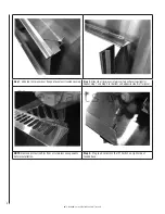
Step 1.
Slide top trim pieces over fl ange of panel until seated squarely.
Step 2.
Slide side trim pieces into place (top will overlap slightly).
Repeat Step 1 and Step 2 for bottom and opposite side trim for panel.
NOTE:
Remove protective fl im from all stainless components
before installation.
Step 3.
Plug lead wires into the IPI Switch on right side of
facade base.
f i r e - p a r t s . c o m