32
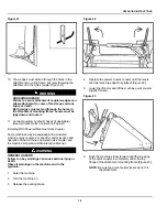
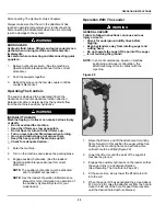
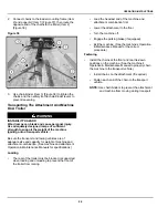
Figure 41
C221894b
1.
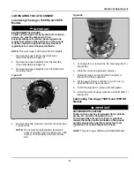
Remove 4 bolts (Item 1) from the cover (item 2)
[Figure 41].
2.
Lift the cover (Item 2) [Figure 41] off the auger.
NOTE:
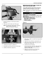
The motor drive chain should be lubricated
every 50 hours or as needed.
(See Service Schedule on Page 30)
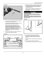
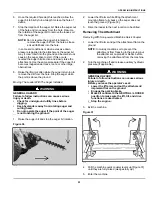
Figure 42
C221897c
3.
Lubricate the chain (Item 1) [Figure 42].
4.
Reinstall the cover (Item 2) [Figure 41] on the auger.
5.
Install the 4 bolts (Item 1) [Figure 41].
REMOVING AND INSTALLING STANDARD /
HEAVY DUTY AUGER TEETH
Various types and styles of auger points and teeth are
available for different applications. The most common
types are shown below for replacing components.
NOTE:
Your model may vary slightly, but the procedure is
the same.
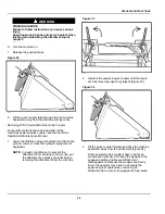
WARNING
IMPACT AND INJECTION HAZARDS
Flying debris or pressurized fluids can cause serious
injury or death.
Wear safety glasses to prevent eye injury when any
of the following conditions exist:
•
When fluids are under pressure.
•
Flying debris or loose material.
•
Engine is running.
•
Tools are being used.
◂
W-2019
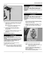
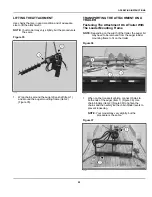
Figure 43
C221418a
1.
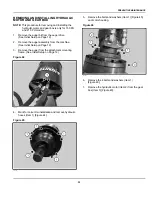
Remove the nut (Item 1) and bolt from the point (Item
4) [Figure 43].
2.
Replace the nut and bolt when replacing the point.
3.
Remove the 4 nuts and 4 bolts (Item 2) to remove
the teeth (Item 3) [Figure 43].
4.
Position the tooth on the auger.
Ensure the direction of the tooth cutting edge faces
the same direction of the auger point (Item 4)
[Figure 43] cutting edge.
5.
Replace the 4 nuts (Item 2) and 4 bolts when
installing the teeth (Item 3) [Figure 43].
Summary of Contents for Auger 75 DDH
Page 2: ......
Page 12: ...10 Figure 4 C221899a SAFETY AND TRAINING RESOURCES ...
Page 29: ......
Page 52: ...50 troubleshooting 29 W warranty 48 welding safety 7 ALPHABETICAL INDEX ...
Page 53: ......

