background image

8

PUBLICATIONS AND TRAINING

RESOURCES

The following publications are also available for your
Ignite Attachments machine. Access them online at
Igniteattachments.com.

C221554

Operation & Maintenance
Manual

Complete instructions on
the correct operation and
the routine maintenance
of your attachment.
7519274

For the latest information on Ignite Attachments products
and the Ignite Attachments Company, visit our website at
Igniteattachments.com

SAFETY AND TRAINING RESOURCES

Summary of Contents for Auger 75 DDH

Page 1: ...USA Original Instructions 2023 Ignite Attachments All Rights Reserved Operation Maintenance Manual Auger Auger 75 DDH S N B6EM00101 Above Auger 165 DDH S N B6EN00101 Above Auger 150 PH S N B6EP00101 Above Auger 210 PH S N B6ER00101 Above ...

Page 2: ......

Page 3: ...ACHMENT SIGNS 9 OPERATING INSTRUCTIONS 12 INITIAL SETUP 12 Installing The Auger On The Loader Attachment Mounting Frame 12 Removing The Auger From The Loader Attachment Mounting Frame 12 Installing The Hydraulic Hoses On The Auger 12 Installing The Auger Bit 12 DAILY INSPECTION 14 Inspecting Attachment Mounting Frame 14 Inspecting The Machine Quick Coupler 14 OPERATING PROCEDURE WITH LOADERS 15 Ap...

Page 4: ...ON DRIVES 34 ATTACHMENT STORAGE AND RETURN TO SERVICE 37 Attachment Storage 37 Return To Service 37 SPECIFICATIONS 38 ATTACHMENT SPECIFICATIONS 38 Auger Dimensions 38 Performance Specifications 39 Attachment Capacities 39 TORQUE SPECIFICATION FOR BOLTS 40 Torque For General SAE Bolts 40 Torque For General Metric Bolts 40 HYDRAULIC CONNECTION SPECIFICATIONS 42 O ring Face Seal Connection 42 Straigh...

Page 5: ... Serial Number Figure 1 C221397a Always use the serial number Item 1 Figure 1 of the auger when requesting service information or when ordering parts Earlier or later models identification made by serial number may use different parts or it may be necessary to use a different procedure in doing a specific service operation FOREWORD ...

Page 6: ...r Bits Standard duty bits and teeth Heavy duty bits and teeth Extensions Hex extension 610 mm 24 in Hex extension 914 mm 36 in Adapters Hex to round adapter 5 08 cm 2 0 in to 6 51 cm 2 563 in Augers With Standard Duty Bits 15 24 cm 6 in double flight 22 86 cm 9 in double flight 30 48 cm 12 in double flight 38 1 cm 15 in double flight 45 72 cm 18 in double flight 60 96 cm 24 in double flight Augers...

Page 7: ...before operating attachment if applicable In addition to the design and configuration of equipment hazard control and accident prevention are dependent upon the awareness concern prudence and proper training of personnel involved in the operation transport maintenance and storage of equipment Check that the attachment is securely fastened to the machine Make sure all the machine controls are in th...

Page 8: ...ment is a potential fire hazard The operator s area engine compartment and engine cooling system must be inspected every day and cleaned if necessary to prevent fire hazards and overheating All fuels most lubricants and some coolant mixtures are flammable Flammable fluids that are leaking or spilled onto hot surfaces or onto electrical components can cause a fire Operation Do not use the machine w...

Page 9: ...st System The spark arrester exhaust system is designed to control the emission of hot particles from the engine and exhaust system but the muffler and the exhaust gases are still hot Check the spark arrester exhaust system regularly to make sure it is maintained and working properly Use the procedure in the Operation Maintenance Manual for cleaning the spark arrester muffler if equipped Welding A...

Page 10: ...nline at Igniteattachments com C221554 Operation Maintenance Manual Complete instructions on the correct operation and the routine maintenance of your attachment 7519274 For the latest information on Ignite Attachments products and the Ignite Attachments Company visit our website at Igniteattachments com SAFETY AND TRAINING RESOURCES ...

Page 11: ...9 ATTACHMENT SIGNS NOTE The location of the decals is the same on the 75 DDH 165 DDH 150 PH and 210 PH models Figure 3 C221403b SAFETY AND TRAINING RESOURCES ...

Page 12: ...10 Figure 4 C221899a SAFETY AND TRAINING RESOURCES ...

Page 13: ...drive unit and on the auger bit 73536420IG 7353640IG 2 DRILLING ELECTRIC SHOCK WARNING Located on both sides of the drive unit 7130147 7130147 3 DO NOT ENTER EXIT ON THIS SIDE WARNING DECAL Located on the mounting frame 7130141 7130141 SAFETY AND TRAINING RESOURCES ...

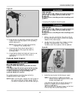
Page 14: ... Install a lifting device Item 1 Figure 6 around the auger drive Item 2 and raise the auger and mounting frame Item 3 slightly 2 Remove the nut Item 5 Figure 6 3 Remove the bolt Item 4 and lock washer Item 6 Figure 6 4 Remove the loader attachment mounting frame Item 3 Figure 6 5 Lower the auger drive Item 2 Figure 6 fully Installing The Hydraulic Hoses On The Auger Figure 7 C221601b 1 Install the...

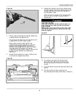
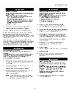
Page 15: ...re 8 Figure 9 C221407a 2 Raise the auger drive and align the hole on the auger drive shaft Item 1 with the hole in the auger bit Item 2 Figure 9 3 Slide the auger bit onto the shaft Figure 10 C221408a 4 Install the pin and locking clip Item 1 Figure 10 OPERATING INSTRUCTIONS ...

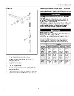
Page 16: ...h Both wedges must extend through the holes in the attachment mounting frame Levers must be fully down and locked W 2715 EF Figure 12 NA3448a Lower down the quick coupler levers until they are fully engaged in the locked position Figure 12 wedges fully extended through the attachment mounting frame holes The levers and wedges must move freely Figure 12 Figure 13 NA3450A The wedges must extend thro...

Page 17: ...ads of specified densities are approved for each model Never use attachments implements or buckets which are not approved by Ignite Attachments W 2662 WARNING INSTABILITY HAZARD Excessive load can cause loss of control or tipping leading to serious injury or death DO NOT exceed Rated Operating Capacity ROC W 2053 Warranty on this implement is void if used on a non approved carrier Contact your Ign...

Page 18: ...alling The Attachment Installing With Non powered Machine Quick Coupler The attachment mounting frame for the attachment has a top flange that is designed to receive the top edge of the machine quick coupler and the lower part of the frame is designed to receive the quick coupler wedges WARNING GENERAL HAZARD Failure to obey warnings can cause serious injury or death Obey all warnings on the machi...

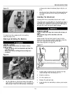
Page 19: ...machine off and exit the machine See Entering And Exiting The Machine on Page 16 WARNING GENERAL HAZARD Failure to follow instructions can cause serious injury or death Before you leave the operator s seat Lower the lift arms and put the attachment implement flat on the ground Engage the parking brake Move all controls to the NEUTRAL LOCKED position to make sure the lift tilt and drive functions a...

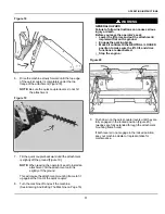
Page 20: ...ine quick coupler For specific control location and operation of the machine s powered quick coupler see the machine s Operation Maintenance Manual WARNING GENERAL HAZARD Failure to obey warnings can cause serious injury or death Obey all warnings on the machine and in the manuals W 2744 1 Enter the machine 2 Turn the machine on 3 Release the parking brake Figure 22 NA3453A 4 Operate the powered q...

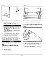
Page 21: ...wered quick coupler until the levers are fully engaged in the locked position Figure 25 wedges fully extended through the attachment mounting frame holes If both levers do not engage in the locked position see your machine dealer or representative for maintenance WARNING CRUSHING HAZARD Failure to secure attachment coupler wedges can allow attachment to come off and cause serious injury or death B...

Page 22: ...es are not twisted or contacting any moving parts of the machine or attachment NOTE It may be necessary to loosen the quick couplers on the attachment hydraulic hoses to remove any twists in the hose WARNING IMPACT AND INJECTION HAZARDS Flying debris or pressurized fluids can cause serious injury or death Wear safety glasses to prevent eye injury when any of the following conditions exist When flu...

Page 23: ...e the same size and type WARNING BURN HAZARD Hydraulic fluid tubes fittings and quick couplers can get hot when running machine and attachments implements Be careful when connecting and disconnecting quick couplers W 2220 Connecting The Hydraulic Quick Couplers WARNING BURN HAZARD Hydraulic fluid tubes fittings and quick couplers can get hot when running machine and attachments implements Be caref...

Page 24: ... brake 3 Engage auxiliary hydraulics See the loader s Operation Maintenance Manual for correct procedure NOTE The auxiliary hydraulics must be activated prior to attachment operation NOTE See the loader s Operation Maintenance Manual for more information on operation of the Auxiliary Hydraulic System for your model loader Operation With The Loader WARNING GENERAL HAZARD Failure to follow instructi...

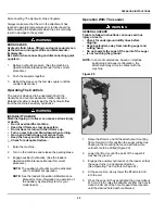
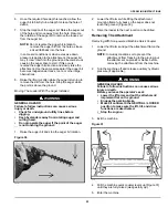
Page 25: ... bystanders away from rotating auger and cutting head Do not operate the auger if the point of the auger is not touching the ground W 2711 1 Raise the auger bit and stop the auger bit rotation Figure 30 C221412a 2 Lower the lift arms while tilting the attachment mounting frame fully back so the auger does not touch the ground Figure 30 3 Drive the loader to the next location to be drilled Removing...

Page 26: ...d Lower or close the hydraulic equipment if equipped NOTE In muddy conditions or to prevent the attachment from freezing to the ground put the attachment on planks or blocks before removing the attachment from the machine Figure 33 NA3453A 2 Operate the powered quick coupler until the levers are fully raised wedges fully raised Figure 33 Figure 34 NA3447b 3 Tilt the quick coupler forward and drive...

Page 27: ...ening The Attachment On A Trailer With The Loader Mounting Frame NOTE Depending on the width of the trailer the auger bit may have to be removed from the auger loader mounting frame to fit on the trailer Figure 36 C113130a 1 When on the transport vehicle connect chains to both ends of the auger Item 1 Figure 36 Use chain binders Item 2 Figure 36 to tighten the chains and then safely tie the chain ...

Page 28: ...combination See machine and attachment Operation Maintenance Manuals for specifications Loading The rear of the trailer must be blocked or supported when loading and unloading to prevent the front of the trailer from raising Load the heaviest end of the machine and attachment combination first Lower the attachment to the floor Turn the machine off Engage the parking brake if equipped Exit the mach...

Page 29: ......

Page 30: ...nstructed to do so in manual Always lower the attachment implement to the ground before lubricating or servicing Avoid contact with leaking hydraulic fluid or diesel fuel under pressure It can penetrate skin or eyes Stop cool and clean engine of flammable materials before checking fluids Keep body loose objects and clothing away from moving parts electrical contacts hot parts and exhaust Safety gl...

Page 31: ...o connect the flow meter Use the following trouble shooting chart to locate and correct problems which most often occur with the attachment PROBLEM CAUSE CORRECTION Auger does not mount properly on the attachment mounting frame Attachment mounting frame wedges are not fully retracted Fully retract attachment mounting frame wedges Mud dirt or stones are lodged between the attachment mounting frame ...

Page 32: ...rvice Interval hours and annually 10 50 Annually Hydraulic Hoses Fittings Check for damage or leaking hydraulic hoses or fittings Replace if necessary O Decals Check for damaged or missing decals Replace if necessary O Auger Bits Check points and teeth Repair if damaged or replace if necessary O Drive Unit Output Shaft Check for damage Repair if damaged or replace if necessary O Planetary Reductio...

Page 33: ...be replaced after the first 50 hours of operation and then after every 1000 hours or once annually whichever comes first Figure 40 C222042a 5 To change the oil remove the fill drain plug Item 1 Figure 40 6 Drain the oil into an approved container 7 Rotate the auger so the fill drain hole Item 1 Figure 40 is facing upwards 8 Fill the auger reservoir with 621 0 ml 21 0 oz of 80W 90 Premium Gear Lubr...

Page 34: ...ary slightly but the procedure is the same WARNING IMPACT AND INJECTION HAZARDS Flying debris or pressurized fluids can cause serious injury or death Wear safety glasses to prevent eye injury when any of the following conditions exist When fluids are under pressure Flying debris or loose material Engine is running Tools are being used W 2019 Figure 43 C221418a 1 Remove the nut Item 1 and bolt from...

Page 35: ... from the machine See Initial Setup on Page 12 3 Remove the auger from the attachment mounting frame See Initial Setup on Page 12 Figure 44 C221601a 4 Mark for correct re installation and remove hydraulic hoses Item 1 Figure 44 Figure 45 C221602a 5 Remove the bolts and washers Item 1 Figure 45 and motor housing Figure 46 C221603a 6 Remove the 4 bolts and washers Item 1 Figure 46 7 Remove the hydra...

Page 36: ...gine is running Tools are being used W 2019 NOTE This procedure to disassemble and reassemble the chain reduction drives is only for 75 DDH and 165 DDH models Figure 47 C221894a 1 Remove the bolts Item 1 Figure 47 Figure 48 C221894b 2 Remove the cover Item 2 Figure 48 Figure 49 C221896a 3 Locate and remove the spring clip Item 2 that holds the master link Item 1 Figure 49 in place 4 Remove the mas...

Page 37: ... 51 Figure 52 C222047a 8 To assemble place the motor Item 1 on the motor plate Item 2 Figure 52 NOTE The hoses Item 3 Figure 52 should come out of the top of the auger drive Figure 53 C221897a 9 Line up the bolt holes and install the 4 socket head cap screws Item 1 Figure 53 10 Tighten the bolts Item 1 with the lock washers Item 3 and nuts Item 2 Figure 53 See Torque Specification For Bolts on Pag...

Page 38: ...m 1 and place it around the larger drive sprocket Item 2 Figure 55 NOTE Keep the chain ends as even as possible Figure 56 C221897b 13 Bring the two ends of the chain toward the front of the box Figure 56 Figure 57 C221896b 14 Place the chain Item 1 around the drive sprocket Item 2 Figure 57 PREVENTIVE MAINTENANCE ...

Page 39: ...lange lower mounts and all welds on the attachment for wear and damage Check for loose hardware missing guards or damaged parts Replace worn or damaged parts Check for damaged or missing decals Replace if necessary Place the attachment in a dry protected shelter Place the attachment flat on the ground NOTE In muddy conditions or to prevent the attachment from freezing to the ground put the attachm...

Page 40: ... for comparison purposes only and are subject to change without notice Specification s for your individual Ignite Attachments equipment will vary based on normal variations in design manufacturing operating conditions and other factors Figure 60 NA22172a DESCRIPTION 75 AUGER DDH 165 AUGER DDH 150 AUGER PH 210 AUGER PH WIDTH A 363 2 mm 14 3 in 363 2 mm 14 3 in 287 0 mm 11 3 in 287 0 mm 11 3 in WIDT...

Page 41: ...pm 90 8 L min 24 U S gpm 88 rpm 82 rpm 98 4 L min 26 U S gpm 89 rpm 106 0 L min 28 U S gpm 97 rpm 113 6 L min 30 U S gpm 104 rpm TORQUE AUGER 75 DDH AUGER 165 DDH AUGER 150 PH AUGER 210 PH 13790 kPa 137 9 bar 2000 psi 910 N m 671 ft lb 2016 N m 1487 ft lb 1452 N m 1071 ft lb 2084 N m 1537 ft lb 17237 kPa 172 4 bar 2500 psi 1138 N m 839 ft lb 2516 N m 1856 ft lb 1813 N m 1337 ft lb 2605 N m 1921 ft...

Page 42: ...5 N m 150 165 ft lb 5 8 170 190 N m 125 140 ft lb 240 260 N m 175 190 ft lb 285 310 N m 210 230 ft lb 3 4 300 330 N m 220 245 ft lb 410 450 N m 300 330 ft lb 490 540 N m 360 400 ft lb 7 8 450 490 N m 330 360 ft lb 645 710 N m 475 525 ft lb 600 650 N m 815 880 ft lb 1 645 710 N m 475 525 ft lb 985 1085 N m 725 800 ft lb 1220 1360 N m 900 1000 ft lb 1 1 8 880 975 N m 650 720 ft lb 1425 1600 N m 1050...

Page 43: ...5 N m 78 85 ft lb 123 137 N m 91 110 ft lb M14 125 140 N m 90 100 ft lb 160 180 N m 118 133 ft lb 190 210 N m 140 155 ft lb M16 190 210 N m 140 155 ft lb 255 285 N m 188 210 ft lb 300 330 N m 225 245 ft lb M18 260 290 N m 190 215 ft lb 345 385 N m 255 285 ft lb 420 460 N m 310 340 ft lb M20 370 410 N m 275 300 ft lb 490 550 N m 360 405 ft lb 590 650 N m 440 490 ft lb M22 500 550 N m 370 400 ft lb ...

Page 44: ...and install the fitting Loosen the nut and install the fitting Tighten the nut until the washer Item 3 Figure 62 is tight against the surface Tubelines And Hoses Replace any tubelines that are bent or flattened They will restrict flow which will slow hydraulic action and cause heat Replace hoses which show signs of wear damage or weather cracked rubber Always use two wrenches when loosening and ti...

Page 45: ... the primary seal the O ring Item 2 is the secondary seal and helps absorb vibration and pressure pulses at the connection Figure 64 If necessary the O ring flare fitting can be used without an O ring Use the following procedure to tighten the O ring flare fitting Figure 65 TS1619 Tighten the nut until it contacts with seat Make a mark across the flats of both the male and female parts of the conn...

Page 46: ...ing to a new hose tubeline NOTE O ring flare fittings are not recommended in all applications Use the standard flare fittings in these applications Do not use an O ring flare fitting when a copper bonnet orifice is used When tightened the connection at the bonnet may distort the flare face and prevent it from sealing Figure 66 P13572a Use a standard flare fitting Item 1 Figure 66 as shown Figure 6...

Page 47: ...ne hex flex maximum Do not over tighten the port seal fitting NOTE If a torque wrench cannot be used use the hex flat tightening method as an approximate guideline NOTE Port seal fittings are not recommended in all applications Use O ring boss fittings in these applications Figure 69 P13571a Do not use port seal fittings when a thread in orifice Item 1 Figure 69 is used in the port The orifice may...

Page 48: ...em 2 Figure 71 and remove the hose from the fitting Figure 72 P91854a 4 To install the hose install the retainer clip Item 1 Figure 72 in the fitting Figure 73 P91855a 5 Install the hose Item 1 Figure 73 into the fitting 6 Press down on the hose until the top of the hose flare is fully seated in the fitting and the retainer clip is over the top of the hose flare Item 2 Figure 73 SPECIFICATIONS ...

Page 49: ...47 Figure 74 P91856a 7 Push the grommet Item 1 down and over the top of the fitting Item 2 Figure 74 SPECIFICATIONS ...

Page 50: ...8 ATTACHMENT IMPLEMENT WARRANTY A statement explaining the terms and conditions of the warranty coverage that applies to your attachment implement is available by visiting Igniteattachments com WARRANTY ...

Page 51: ... 18 installing hydraulic hoses 12 L lifting the attachment 25 lubricating the auger lubrication locations 31 M maintenance safety 6 moving with the auger installed loader 23 O operating the controls loader 22 operation of the auger loader 22 P publications and training resources 8 R removing and installing hydraulic motor and gear box hydraulic motor 33 removing and installing light standard duty ...

Page 52: ...50 troubleshooting 29 W warranty 48 welding safety 7 ALPHABETICAL INDEX ...

Page 53: ......

Page 54: ...s mineral oils and phthalates which are known to the State of California to cause cancer and birth defects or other reproductive harm For more information go to www P65Warnings ca gov 2023 Ignite Attachments All rights reserved Reference Information Product Serial Number Engine Serial Number Dealer Information ...

Reviews: