1
2
3
4
5
6
Connect the camera's video input (yellow) and power supply (red) connectors to the BNC extension cables. Then
connect the BNC video input (yellow) to the video input port on the rear panel. (Repeat Step 1 for the remaining
cameras.)
Connect the mouse to the USB Port on the front or back panel of the DVR.
Depending on the monitor port, connect the HDMI or VGA cable from your monitor to the HDMI or VGA Port on
the rear panel.
Connect the camera's power supply (red) to the power splitter. Then connect the other end of the power splitter
to the power adapter for Cameras and plug in the adapter to a wall outlet. (Repeat Step 2 to connect the camer-
as to the second set of power splitter and power adapter.)
Connect the power adapter for DVR to the DC 12V port on the rear panel and the power plug into a wall outlet.
The DVR will automatically power on and the startup wizard will appear on your monitor.
Connect one end of the Ethernet cable into your router’s LAN port, and the other end of the cable to the Ethernet
port on the rear panel.
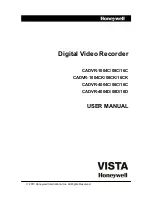
1.4 Connecting the DVR
HDMI
VGA
RS485
+ -
LAN
5
7
6
3
4
1
2
8
VIDEO INPUT
12V
CAUTION
RISK OF ELECTRIC SHOCK
DO NOT OPEN
CAUTION : TO REDUCE THE RISK OF ELECTRICAL SHOCK
DO NOT OPEN COVERS. NO USER SERVICEABLE
PARTS INSIDE. REFER SERVICING TO QUALIFIED
SERVICE PERSONNEL.
WARNING : TO PREVENT FIRE OR SHOCK HAZARD. DO NOT
EXPOSE UNITS NOT SPECIFICALLY DESIGNED
FOR OUTDOOR USE TO RAIN OR MOISTURE.
AUDIO
OUTPUT
3
1
2
4
AUDIO
INPUT
1
2
5
3
4
6
9
Summary of Contents for HomeGuard HGDVK-44402
Page 1: ...Helpdesk Technical Support www iget eu cs helpdesk centrum cs https helpdesk intelek cz...
Page 6: ...CONNECTING YOUR SYSTEM 1 4...
Page 15: ...2 BASIC OPERATION 13...
Page 24: ...3 CONNECTING SMART DEVICE 22...
Page 30: ...CONNECTING TO PC MAC 4 28...
Page 38: ...5 TECHNICAL SUPPORT 36...