


PI16xx PI18xx
Electronic pressure sensor
14
6 Installation G1 sealing cone with coupling nut (PI18xx)
Before installing and removing the unit: Make sure that no pressure is applied to the system and
there is no medium in the pipe or tank.
u
Note dangers related to machine / medium temperatures.
The unit must only be installed in an ifm process connection with G1 sealing cone designed for
this.
Information about available adapters at:
u
Observe the instructions of the adapter.
u
Ensure that the sensor is pressed against the metallic stop in the front area in contact with the
product by the coupling nut. This must be independent of whether an adapter with a metallic
sealing edge or an O-ring upstream of the stop (as a media-side seal) is used.
w
If the unit is installed in a 1“ thread without a metallic end stop, this will lead to seal failure.
The sensor series PIx7xx, PMx7xx and PI26xx are available for installation in 1" threaded
sleeves with a suitably designed sensing face.
2
3
4
1
34
46
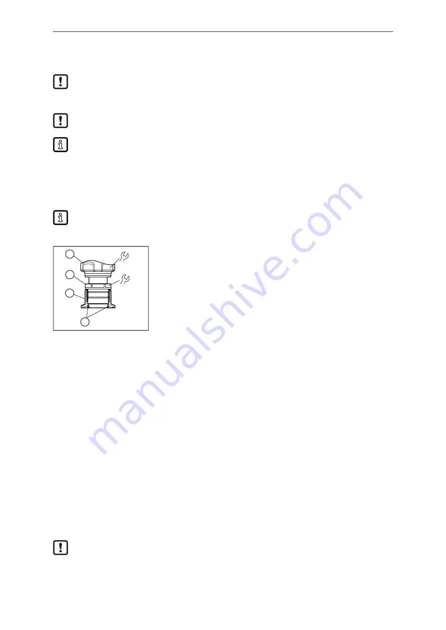
1:
Sensor
2:
Threaded sleeve
3:
Process connection
4:
O-ring (if used)
u
Lightly grease the thread of the threaded sleeve (2) using a lubricating paste which is suitable and
approved for the use case.
u
Insert the sensor (1) into the process connection (3).
u
Slide the threaded sleeve (2) to the internal thread of the process connection (3) and screw it in
loosely.
u
Align the sensor (1) and tighten the threaded sleeve (2) with a spanner, holding the sensor (1) in its
alignment. Tightening torque 20 Nm.
The process adapter can be adapted to different process connections.
Options are as follows:
1: Installation in process adapter with sealing ring
u
Insert the sealing ring into the groove of the adapter before mounting the sensor.
u
Use a suitable O-ring approved for the application in hygienic applications.
Use of welding adapters:
u
During the welding process, make sure that the adapter is not deformed and that the sealing area
is not affected.
u
Observe the instructions and data sheet of the adapter used.
u
Use brass mandrel E30435 for optimised heat conduction.
When reworking the weld seam:
u
Leave out or protect the sealing area.
2: Installation in process adapter with metallic sealing edge


