20
8.3 Connection of external feedback contacts
External feedback contacts can be integrated in the automatic or manual
operating mode. The feedback contacts have to be connected in series between
the operating voltage and K1_K2 (→ 8 Operating modes / table, fig. B and D).
8.4 Internal test function
Type 4 safety light grids continuously perform internal tests. Faults are detected
within the response time of the respective model leading to switch-off (response
times → 12 Technical data).
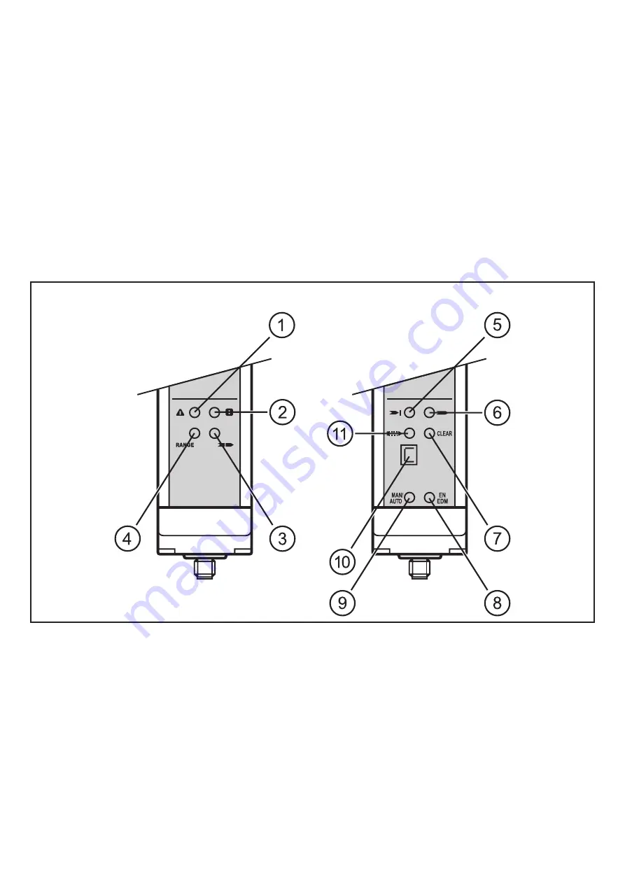
9 Operating and display elements
transmitter
receiver
1: LED (red)
2: LED (green)
3: LED (yellow)
4: LED (orange)
5: LED (red)
6: LED (green)
7: LED (yellow)
8: LED (yellow)
9: LED (yellow)
10: Display
11: LED (orange)
9.1 LED indicators for optical alignment
The indication LEDs of the receiver help to correctly align the transmitter and the
receiver with each other.


