13
UK
• "Controlled via process interface" (e�g� by PLC)
The device is controlled via the command "O" (→
software manual)�
• "User-defined states"
The user-defined states are changed with the processing of codes (e�g� code
found, code matches the reference, code quality outside the threshold level,
etc�)�
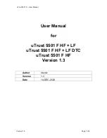
6.2 Wiring example
In the wiring example, the image capture is triggered with a proximity sensor�
The device can be triggered externally:
• via Ethernet
• via a proximity sensor connected to the trigger input
3
1
2
4
5
1
2
3
4
4
2
1
3
5
DC 24 V
+ -
IN
IN
1
2
3
4
5
①
: O2I5xx device
②
: notebook for
parameter setting
③
: industrial PC
for evaluation and
triggering
④
: proximity sensor
⑤
:
voltage source
Fig� 6: Wiring example of a trigger circuit
An adapter cable (Y cable) is available for external trigger sensors:
www�ifm�com