


Reviews:
No comments
Related manuals for DTE603

TLX-7000-FLRAILKIT
Brand: IDEAL Pages: 10

Varixx UMS 4401 SPCD
Brand: Grundig Pages: 47

BBL-4
Brand: Vestil Pages: 6

R7F4DC-DAC16D-H
Brand: M-system Pages: 8
4543-D2
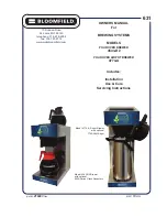
Brand: Bloomfield Pages: 16

Shapeoko XL
Brand: Carbide 3D Pages: 34

USB-DIO96H
Brand: Measurement Computing Pages: 27

AQUACIAT POWER LD 602R-3500R
Brand: CIAT Pages: 56

YT-1711
Brand: YATO Pages: 36

KPCI-PIO24
Brand: Keithley Pages: 66

Devicenet R7F4DD-DA16B-C
Brand: M-system Pages: 7

IB2S-A
Brand: ATL Pages: 46

KCSPM3648
Brand: Affordable Wheelchair Lifts Pages: 74

PAV-AOM8C
Brand: Savant Pages: 2

LV50WE
Brand: Bishamon Pages: 7

510-120
Brand: morse Pages: 6

SCS 661
Brand: Raven Pages: 59

1791-0A32 B Series
Brand: Allen-Bradley Pages: 12


