Installation instructions
RFID compact unit
DTE601DTE602DTE604DTE605
UK
8029371
1 / 00
04 / 2020
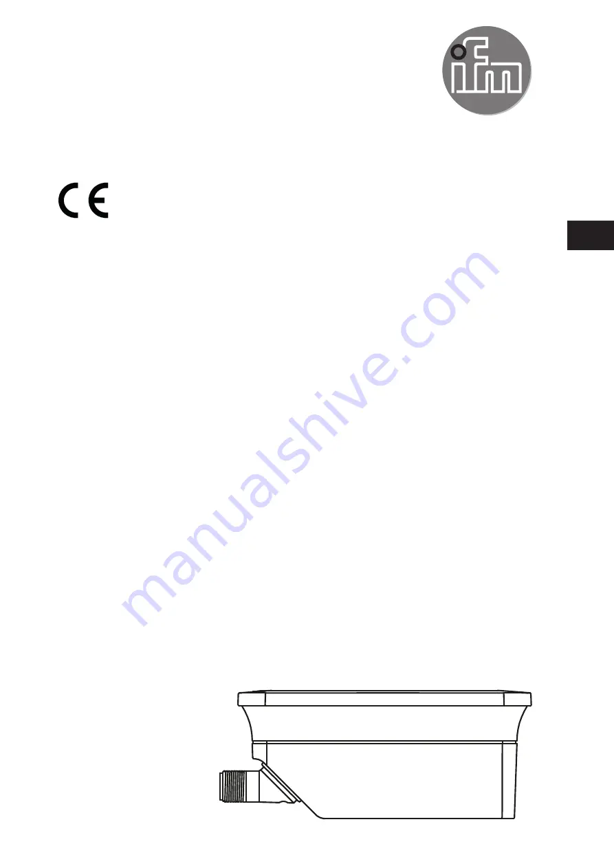
Page 1: ...Installation instructions RFID compact unit DTE601 DTE602 DTE604 DTE605 UK 80293711 00 04 2020 ...
Page 2: ...tion instructions 8 6 2 Notes on ID tag mounting 8 6 3 Avoiding interference 8 6 4 Mechanical design 9 6 5 Installation options 9 6 5 1 Installation with angle bracket E80335 9 6 5 2 Installation with mounting device E80336 10 6 5 3 Installation with fixing bars E80337 10 6 6 Mounting distances 11 6 7 Positioning of the ID tags 11 7 Electrical connection 12 7 1 Voltage supply PWR 12 7 2 Ethernet 1...
Page 3: ... module status 19 8 4 2 LED Net network status 20 8 5 LED indicators DTE604 DTE605 21 8 5 1 LED SF 21 8 5 2 LED BF 21 9 Scale drawing 22 10 Technical data 22 10 1 Data sheet 22 10 2 Device manual 22 11 Maintenance repair and disposal 22 12 Approvals standards 23 12 1 Radio approvals 23 12 1 1 Overview 23 12 1 2 Europe EC declaration of conformity 23 12 1 3 USA 23 12 1 4 Canada 24 12 1 5 Taiwan 24 ...
Page 4: ...ctronic gmbh No part of these instructions may be reproduced and used without the consent of ifm electronic gmbh All product names pictures companies or other brands used on our pages are the property of the respective rights owners 2 Safety instructions The device described is a subcomponent for integration into a system The manufacturer is responsible for the safety of the system The system manu...
Page 5: ...fied personnel authorised by the machine operator Protect the device and the cables against damage Use the device outside petrol stations fuel depots chemical plants or blasting operations Do not transport and store any flammable gases liquids or explosive substances near the device Operation of the device can affect the function of electronic devices that are not correctly shielded Disconnect the...
Page 6: ...s specified in the data sheet 3 1 Configuration via Ethernet interface 10 Mbps and 100 Mbps TCP IP Transport Control Protocol Internet Protocol IT functionality HTTP server M12 twisted pair 4 Items supplied DTE60x RFID compact unit Installation instructions The device is supplied without installation and connection accessories In the event of incomplete or damaged items supplied please contact ifm...
Page 7: ...unit DTRHF HLRWPNUS03 13 56 Mhz rectangular 2 watts Fig 1 Overview DTE601 5 3 Overview DTE602 Art no Function Type designation Operating frequency Type Max transmitter power DTE602 RFID compact unit DTRHF HLRWEIUS03 13 56 Mhz rectangular 2 watts Fig 2 Overview DTE602 5 4 Overview DTE604 Art no Function Type designation Operating frequency Type Max transmitter power DTE604 RFID compact unit DTRHF H...
Page 8: ...ccessories www ifm com 6 2 Notes on ID tag mounting Installation of the ID tags in and on metal reduces the read and write distances For positioning the ID tags the RFID compact units are marked with an antenna symbol on the active face It designates the middle of the integrated antenna coil and has to correspond with the middle of the ID tag The orientation of the RFID compact unit axis must corr...
Page 9: ...or installation the following optional accessories are available The device can be mounted without the accessories For installation please use the threaded sleeves on the back of the device The necessary screws are not supplied with the device 6 5 1 Installation with angle bracket E80335 Fig 6 Installation with angle bracket E80335 ...
Page 10: ... clamps can be used E21110 with a rod diameter of 12 mm E20795 with a rod diameter of 14 mm E21109 with a rod diameter of 14 mm Fig 7 Installation with mounting device E80336 6 5 3 Installation with fixing bars E80337 Fig 8 Installation with fixing bars E80337 Fix the device with fixing screws to the designated location ...
Page 11: ...distances Operating mode Distance side A Distance front B Read and write at 100 transmitter power 850 mm 600 mm 6 7 Positioning of the ID tags D Align the ID tag on the antenna central axis Distance D see data sheet Fig 10 Position of the ID tag ...
Page 12: ...ce of 0 5 A must not be exceeded NOTE The IP rating indicated in the data sheet is only guaranteed if the M12 connectors are firmly screwed The unit can be damaged by insufficiently tightened M12 connectors Firmly screw the M12 connectors to the device 7 1 Voltage supply PWR Connect the device to the voltage supply using an M12 connection cable 3 1 2 4 5 Pin Connection 1 24 V DC 2 digital input ou...
Page 13: ...in Connection 1 TD 2 RD 3 TD 4 RD Fig 12 Pin connection fieldbus connection 7 2 1 Factory setting of the Ethernet parameters The following values are preset at the factory Parameter Factory setting IP address 192 168 0 79 Gateway address 192 168 0 100 Subnet mask 255 255 255 0 Auto negotiation on DHCP off The settings can be changed via the web server of the device or via the PC ...
Page 14: ...ust be connected to an earth potential free from external voltage 7 3 1 Mounting plate When the device is fixed on a mounting plate the connection is made via one of the four mounting bolts on the back Note that the plate must be connected with the earth potential Fig 13 Mounting plate ...
Page 15: ...ows Remove all cable connections from the device Insert an electrically conductive bridge between pin 2 and pin 4 on the process connection voltage supply PWR Connect the device to the voltage supply The LEDs of the signal bar yellow are on one after the other Then LED 4 of the signal bar yellow flashes at 8 Hz As soon as the LEDs of the signal bar yellow flash at 8 Hz disconnect the device Remove...
Page 16: ... read written incorrectly If the ID tag has a high receive signal strength all LEDs of the signal bar are on configurable The maximum receive signal strength depends on the type of the ID tag 8 2 2 LED LINK ACT ETH 1 ETH 2 LED green LED yellow Status Note off off no connection to another Ethernet counterpart link status no link on off connection to Ethernet counterpart exists no data exchange link...
Page 17: ...rmware update is necessary and can be executed via the web server PWR LED green on LEDs of signal bar yellow flashing at 8 Hz major error device has to be returned hardware fault or permanent data in the device are corrupt PWR LED green on The LEDs of the signal bar yellow are on one after the other Then LED 4 of the signal bar yellow flashes at 8 Hz reset to factory settings ...
Page 18: ...n off error at device level undervoltage temperature flashing flashing self test starting phase of the device 8 3 2 LED BF LED red LED green Status Note off off no voltage supply check the voltage supply off flashing PROFINET IO controller is in STOP mode off on PROFINET IO controller is in RUN mode flashing off connection to the PROFINET IO controller is established no valid configuration check c...
Page 19: ...ner Check the parameter setting of the configuration assembly off on normal operation Connection to the EtherNet IP scanner is established The device is configured The data transfer is running flashing off minor error A connection to the EtherNet IP scanner was not established Check the voltage supply Check the configuration of the device on off major error Software hardware error of the device Re...
Page 20: ... Check the configuration of the device via EtherNet IP scanner off on connection exists At least one EtherNet IP connection to the device was established flashing off timeout of the connection A timeout was found with one of the existing EtherNet IP connections Check the status of the connection in the EtherNet IP scanner on off IP address exists already The same IP address as that of the device w...
Page 21: ...ge temperature flashing flashing self test starting phase of the device 8 5 2 LED BF LED red LED green Status Note off off no voltage supply check the voltage supply off flashing connection to host controller exists there is no data exchange off on connection to host controller exists data exchange running flashing off connection to host controller exists there is no valid configuration check conf...
Page 22: ...le on our website www ifm com 11 Maintenance repair and disposal If used correctly no maintenance and repair measures are necessary The device must only be repaired by the manufacturer After use dispose of the device in an environmentally friendly way in accordance with the applicable national regulations Keep the device free from soiling Use glass cleaner as cleaning agent Do not open the device ...
Page 23: ...ce and 2 this device must accept any interference received including interference that may cause undesired operation Changes or modifications made to this equipment not expressly approved by ifm may void the FCC authorization to operate this equipment NOTE This equipment has been tested and found to comply with the limits for a Class A digital device pursuant to part 15 of the FCC Rules These limi...
Page 24: ...roved low power radio frequency device Article 14 Low power radio frequency devices shall not affect aircraft security nor interfere with legal communications If such interference occurs the user shall immediately cease operating the device until improvement is made and the interference no longer exists Legal communications refers to the wireless telecommunication operations that comply with the T...
Page 25: ...25 UK 12 1 6 Australia Use in Australia 12 1 7 Singapore Complies with IDA Standards DB 103032 The Equipment Registration is available on our website at www ifm com ...