background image

10

Since all diagnostic cases can be signalled via the switching output in 

3-wire operation, the analogue output only leaves its measured tempera-

ture value in diagnostic case of category "failure"� This ensures maximum 

use of the analogue output�

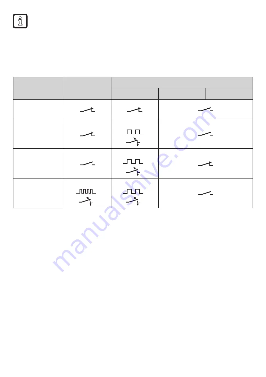
The parameter [dOU1] is used to define how the diagnostic output reacts to diag-

nostic messages:

Normal

Diagnostic message

[dOU1]

Warning

Alarm

Failure

= nc

normally closed
= nc+

normally closed, 

extended

2 Hz

= no+

normally open, 

extended

2 Hz

= Hb

heartbeat

4 Hz

2 Hz

Table 3: Switching signal in diagnostic case

5.3  IO-Link

This unit has an IO-Link communication interface which enables direct access to 

process and diagnostic data� In addition it is possible to set the parameters of the 

unit during operation� Operation of the unit via IO-Link interface requires an IO-

Link capable module (IO-Link master)�
With a PC, suitable IO-Link software and an IO-Link adapter cable communication 

is possible when the system is not in operation�
The IODDs necessary for the configuration of the unit, detailed information about 

process data structure, diagnostic information, parameter addresses and the 

necessary information about the required IO-Link hardware and software can be 

found at www�ifm�com�

Summary of Contents for TAD 91 Series

Page 1: ...Operating instructions Temperature transmitter TADx81 TADx91 80261226 00 03 2017 UK...

Page 2: ...Diagnostic function in 2 wire operation 8 5 2 5 Diagnostic function in 3 wire operation 9 5 3 IO Link 10 6 Installation 11 6 1 Installation of units with G1 Aseptoflex Vario process connection 11 6 2...

Page 3: ...ing applications and environ mental conditions without any restrictions Only use the product for its intended purpose 4 Functions and features Only use the product for permissible media 11 Technical d...

Page 4: ...ic cases that should be signalled 5 2 3 drEd ON only diagnostic cases of category failure ONdr diagnostic cases of categories alarm failure OFF diagnostic cases of categories warning alarm failure 6 C...

Page 5: ...gnostic func tion The transfer of the measured temperature value is interrupted for diagnostic messages depending on the operating mode and the setting of drEd and an ana logue signal according to NE4...

Page 6: ...ically coupled sensor elements NTC PT 1000 the unit automatically detects drifts and errors during temperature measure ment A mean average value is formed from the measured individual NTC and Pt 1000...

Page 7: ...s 65 C Pt 1000 sensor element 2 measures 60 C The mean value 3 is 62 5 C i e both elements deviate by 2 5 K With setting drW 2 C and drA 5 C a warning message would be provided if drEd OFF There would...

Page 8: ...xceeded 125 C 3 Drift alarm threshold drA exceeded 4 Failure of one of the two sensor elements 5 Measured temperature value far outside the measuring range 6 Supply voltage outside the operating range...

Page 9: ...ed and provided by the following analogue signal depending on the setting of FOU FOU2 ON 21 5 mA FOU2 OFF 3 5 mA In the event of undervoltage diagnostic case 6 5 2 3 no diagnostic message is provided...

Page 10: ...itching signal in diagnostic case 5 3 IO Link This unit has an IO Link communication interface which enables direct access to process and diagnostic data In addition it is possible to set the paramete...

Page 11: ...allation using an adapter with metal to metal seal Installation using an adapter with sealing ring Installation to G 1 flange The sealing ring on the sensor is used as process seal The upper sealing a...

Page 12: ...h A 3 certification for the process connection Do not install the unit at the lowest point of the pipe or tank position 5 in order that the medium can run off the area of the measuring element 6 4 Use...

Page 13: ...2 to cULus Disconnect power Connect the unit as follows 2 wire operation 3 wire operation 4 3 2 1 L BN 1 WH 2 OUT BN WH BK BU 4 1 3 2 OUT2 L L OUT1 Colours to DIN EN 60947 5 2 BK black BN brown BU blu...

Page 14: ...value AEP Analogue end point for measured temperature value drW Drift warning threshold If this value of the temperature deviation is exceeded a diagnostic message of the category warning is provided...

Page 15: ...gue signal when a diagnostic case is signalled Instead of the measured temperature value a defined current value according to Namur NE43 is provided On 21 5 mA OFF 3 5 mA dOU1 Response of the diagnost...

Page 16: ...tegory alarm In 3 wire operation all diagnostic cas es can be signalled via the diagnostic switching output except those used for drift monitoring diagnostic cases 1 3 7 5 2 3 30 Wiring fault Check wi...

Page 17: ...cified temperature range 100 Error during parameter setting via IO Link set value of a parameter outside the valid range Repeat parameter setting with admissible parameter values or make a reset reset...

Reviews: