CAN BusTester EC2100
6
5 Electrical connection
5.1 General electrical connection
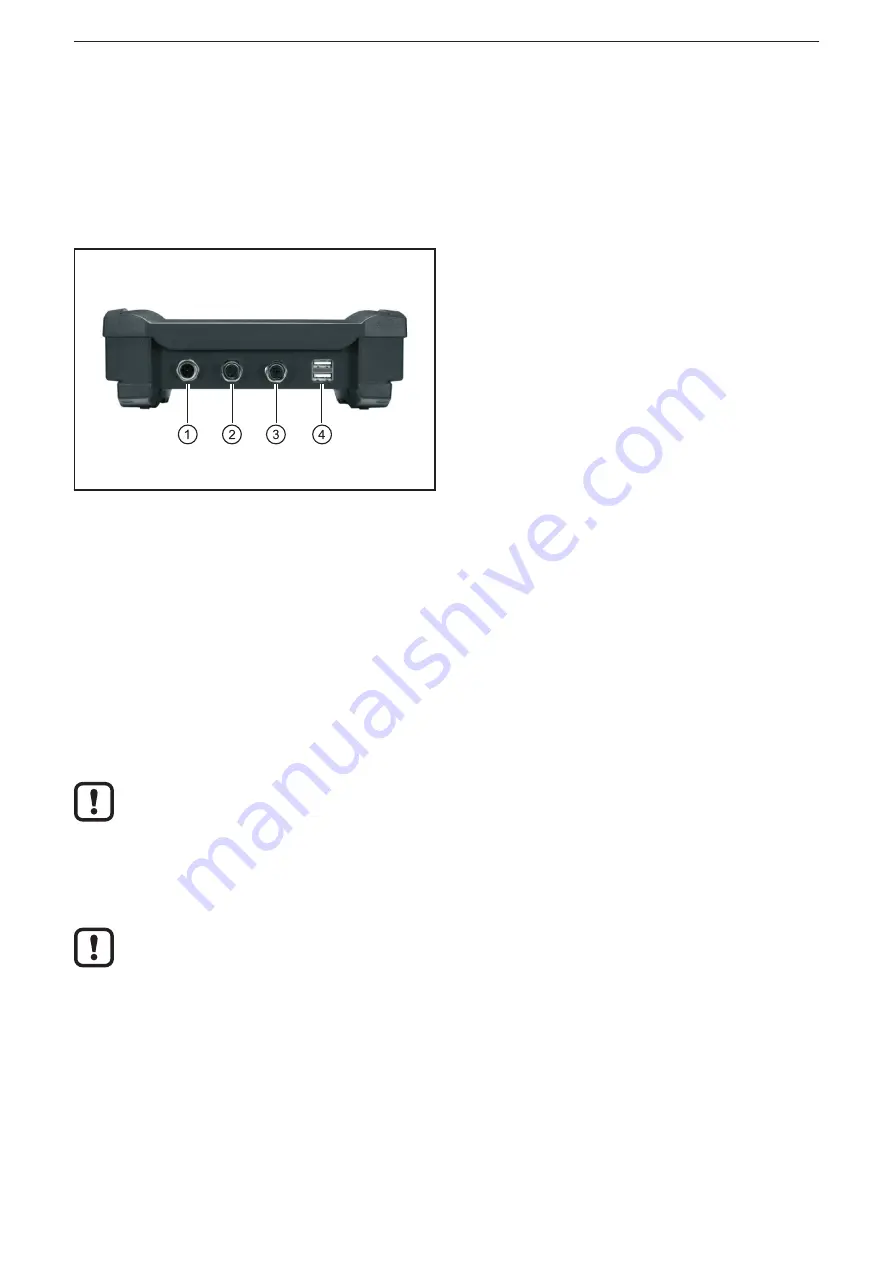
The interfaces to external systems are at the bottom of the device�
CAN bus, USB devices and the LAN network are automatically recognised when
they are connected�
1: Supply, CAN (M12 connector, 5 poles)
2: Supply, CAN (M12 socket, 5 poles)
3: Ethernet (M12 socket, 4 poles, D-coded)
4: USB (2 x type A)
Bottom of the device
Wiring of the connectors (→ 9 Technical data)
5.2 Operating voltage
The supply voltage rate is 10���32 V DC� Supply is effected via the 5-pole M12
connector (1)�
5.2.1 Battery charging
As soon as an external voltage supply is applied, the integrated rechargeable
batteries are charged�
With first setup please note that the device is operated until the integrated
rechargeable batteries are fully charged�
5.2.2 Battery life
When the supply voltage is switched off, battery operation starts at once�
The integrated rechargeable batteries are used as a buffer for short-time
voltage interruptions (≤ 10 min). During operation the voltage is supplied, for
example, via the on-board voltage of a vehicle�
5.3 CAN interface (terminating resistor)
To be able to loop into existing CAN networks the CAN interfaces do not have any
terminating resistor�
5.4 Ethernet interface
► Use a shielded CAT5 cable�
STP, shielded twisted pair, according to EIA/TIA-568� Max� length 100 m


