P
RESET
C
OUNTER
E89005
P
AGE
8
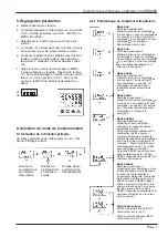
8. Examples for application connections
Count pulses from a
light barrier
Count pulses from contact
closure (programmed
polarity PNP)
Count pulses from a shaft encoder
9. Connections
9.1 Plug connection X1
Terminal 230, 115
No.
1
Output 1, relay contact
2
Output 1, relay contact
3
Output 2, relay output common contact (C)
4
Output 2, relay output normally open contact
(NO)
5
Output 2, relay output normally closed contact
(NC)
6
230 VAC/115 VAC
7
230 VAC/115 VAC
Caution!
For settings –l– and
–l–l– (inverted operation)
the connections of terminal 4 and 5 change as follows:
Terminal AC-Version
No.
4
relay output normally closed contact (NC)
5
relay output normally open contact (NO)
9.2 Plug connection X2
Terminal Designation Function
Function
No.
230 VAC/115 VAC
1
+ 24 VDC
Transmitter voltage
2
GND
0 VDC reference
voltage
3
INP A
count input A
4
INP B
count input B
5
RESET
reset input
6
GATE
gate input
7
KEY
keyboard lock input
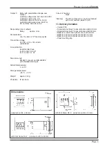
10. Technical Data
Supply voltage:
230 VAC, 115 VAC
50/60 Hz, ±10%,
max. 4 VA
Display:
6 digit, 2-line 7 segment LCD display
with sign
count value 9 mm high characters
preset value 7 mm high characters
symbols for displayed preset and closed
output contacts
Polarity of input signals:
programmable, all inputs in common
Input sensitivity:
approx. 10 kOhm
Count frequency:
via DIL switches separately selectable
for INP A and INP B
30 Hz
10 kHz (7 kHz for input modes E3 and
E4, quadrature inputs)
in case of automatic reset 900 Hz without
count losses (500 Hz for input mode E4)
Min. pulse length of the control inputs:
5 ms
Input sensitivity:
For AC supply voltages
Log “0”: 0...4 VDC
Log “1”: 12...30 VDC
Pulse shape:
variable (Schmitt Trigger characteristic)
Output 1:
Relay with potentialfree make or break
contact
switching voltage max. 250 VAC/125 VDC
switching current max. 3 A
switching current for DC min. 30 mA
switching performance max. 90 W for DC
and max. 750 VA for AC


