


Seite / Page 12
4. Application
The simulator enables the indication of the potentials of the individual input and output channels. In
addition the input channels can be set or reset. To do so, additional switchboxes or analog boxes can be
connected to the simulator. The RS232 and CAN interfaces for system diagnosis, programming and
communication for external components are also available.
Important
: Since the unit has been designed for all controller configurations, not all functions must
always be available. Before connection to the controller its configuration must thus be
checked.
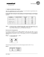
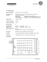
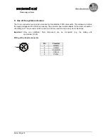
5. Connection simulator
The voltage for the controller and the simulator is supplied via the 2-pole socket. All VBB cables (pin 23,
pin 05 and pin 34) and all GND cables (pin 01 and pin 15) are brought together in one cable. A connection
of the controller via separate potentials is not possible when the simulator is used.
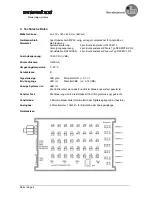
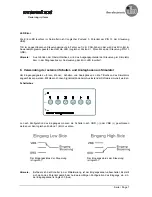
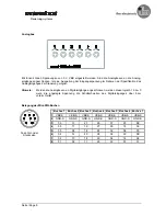
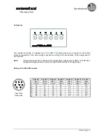
Via the 8-pin sockets on the right-hand side external switchboxes or analog boxes can be connected.
Such a box can be used for 6 input channels at a time (provided that they are configured in the connected
controller). For electromechanical reasons the first 5 sockets combine respectively 6 inputs of a group of 8
(input byte). The 6th socket can be used for the inputs 06,07,14,15,22 and 23, socket 7 for the inputs 30,
31,38 and 39 (see drawing of the unit)
Note:
A switchbox or an analog box can be connected to each socket. It depends on the respective
application and the connected controller (unit configuration) if this makes sense.
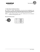
6. Communication interface
The interface (RS232 and CAN) for programming, diagnostic functions and communication is connected
in parallel.
Since the RS232 interface is a pure point-to-point connection, a communication partner (e.g. PC) can only
be connected at one place in the system when a simulator is connected.
According to the valid specification the CAN interface can be used by several participants at the same
time (e.g. communication with display in the application and debugging of the controller software via the
connected PC).
A 120
Ω
Ω
Ω
Ω
terminating resistor is integrated in the simulator to allow the direct connection of further
participants.
Important
: The
TEST
switch must be set to
1
to enable communication between the controller and the
PC programming software
ecolog 100
plus
so that the application software can be loaded into
the controller via this connection.
Steuerungssysteme


