


WSB-H610 PICMG 1.0 CPU Card
Page 39
Pin
Description
Pin
Description
15
SB3V
16
SERIRQ
17
GND
18
+3V
19
PM_SUS_STAT#
20
DRQ#
Table 3-24: TPM Connector Pinouts
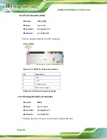
3.2.23 USB Connectors
CN Label:
USB1, USB2, USB3
CN Type:
8-pin header
CN Location:
CN Pinouts:
The USB connectors connect to USB devices. Each pin header provides two USB ports.
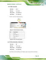
Figure 3-24: USB Connector Pinout Locations
Pin
Description
Pin
Description
1
VCC
2
GND
3
DATA-
4
DATA+
5
DATA+
6
DATA-
7
GND
8
VCC
Table 3-25: USB Port Connector Pinouts
Summary of Contents for WSB-H610
Page 16: ...WSB H610 PICMG 1 0 CPU Card Page 1 Chapter 1 1 Introduction...
Page 21: ...WSB H610 PICMG 1 0 CPU Card Page 6 Figure 1 4 External Interface Panel Dimensions mm...
Page 25: ...WSB H610 PICMG 1 0 CPU Card Page 10 Chapter 2 2 Packing List...
Page 31: ...WSB H610 PICMG 1 0 CPU Card Page 16 Chapter 3 3 Connectors...
Page 59: ...WSB H610 PICMG 1 0 CPU Card Page 44 Chapter 4 4 Installation...
Page 80: ...WSB H610 PICMG 1 0 CPU Card Page 65 Chapter 5 5 BIOS...
Page 116: ...WSB H610 PICMG 1 0 CPU Card Page 101 6 Software Drivers Chapter 6...
Page 129: ...WSB H610 PICMG 1 0 CPU Card Page 114 Appendix A A BIOS Options...
Page 132: ...WSB H610 PICMG 1 0 CPU Card Page 117 Appendix B B One Key Recovery...
Page 140: ...WSB H610 PICMG 1 0 CPU Card Page 125 Figure B 5 Partition Creation Commands...
Page 174: ...WSB H610 PICMG 1 0 CPU Card Page 159 Appendix C C Terminology...
Page 178: ...WSB H610 PICMG 1 0 CPU Card Page 163 Appendix D D Digital I O Interface...
Page 181: ...WSB H610 PICMG 1 0 CPU Card Page 166 Appendix E E Watchdog Timer...
Page 184: ...WSB H610 PICMG 1 0 CPU Card Page 169 Appendix F F Hazardous Materials Disclosure...


