


WAFER-TGL-U SBC
Page 57
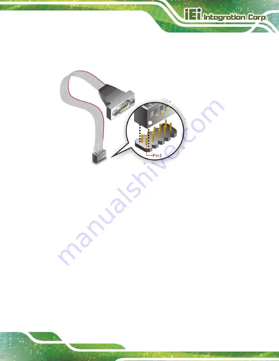
Step 2:
Insert the cable connector.
Align the cable connector with the onboard
connector. Make sure pin 1 on the board and connector line up. Pin 1 on the
cable connector is indicated with a white dot. See
Figure 4-12: Single RS-232 Cable Installation
Step 3:
Secure the bracket
. The single RS-232 connector has two retention screws
that must be secured to a chassis or bracket.
Step 4:
Connect the serial device
. Once the single RS-232 connector is connected to
a chassis or bracket, a serial communications device can be connected to the
system.
Step 0:
4.7.4
SATA Drive Connection
The WAFER-TGL-U is shipped with a SATA drive cable. To connect the SATA drive to the
connector, please follow the steps below.
Step 1:
Locate the SATA connector and the SATA power connector.
The locations of
the connectors are shown in
Chapter 3
.
Step 2:
Insert the cable connector
. Insert the cable connector into the on-board SATA
Summary of Contents for WAFER-TGL-U
Page 11: ...WAFER TGL U SBC Page 1 Chapter 1 1 Introduction...
Page 19: ...WAFER TGL U SBC Page 9 Chapter 2 2 Unpacking...
Page 23: ...WAFER TGL U SBC Page 13 Chapter 3 3 Connectors...
Page 54: ...WAFER TGL U SBC Page 44 Chapter 4 4 Installation...
Page 69: ...WAFER TGL U SBC Page 59 Chapter 5 5 Software Drivers...
Page 72: ...WAFER TGL U SBC Page 62 Appendix A A Regulatory Compliance...
Page 74: ...WAFER TGL U SBC Page 64 B Product Disposal Appendix B...
Page 76: ...WAFER TGL U SBC Page 66 Appendix C C Digital I O Interface...
Page 79: ...WAFER TGL U SBC Page 69 Appendix D D Watchdog Timer...
Page 82: ...WAFER TGL U SBC Page 72 Appendix E E Error Beep Code...
Page 84: ...WAFER TGL U SBC Page 74 Appendix F F Hazardous Materials Disclosure...


